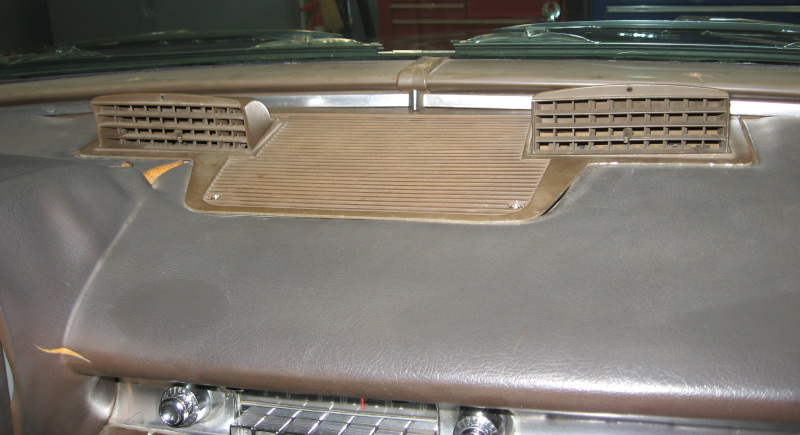
Making a (Mega) Tree

The tree itself is pretty simple – a set of vertical strings of LEDs tapering in at the top to look like a Christmas tree.

LED strings and strips come in 15 meter (15-1/2 ft) lengths. The standard for strings is 50 LEDs wired together – this actually looks like traditional Christmas tree lights. Since this is for outdoor use it is a good idea to go with waterproof connectors. The test string I originally ordered came with interior connectors (foreshadowing).

Since the tree is still experimental I’m starting with a small tree, one around six or seven feet tall. I also decided to build a half circle tree since most people will only see it from one side. I decided to go with a design of 8 strings of lights for a half circle, 16 strings for a full circle. By building a small tree I can use a single strand of lights going both up and down, thus only needing to buy 4 strings of lights.

Surprisingly there aren’t that many choices for LED strings with waterproof connectors. I ended up with Rextin WS2811 strings.

You don’t just hang the lights from the tree. To ensure consistent spacing they make strips of heavy plastic that you plug the lights into. These strips have holes every inch allowing you to space lights two inches, three inches, four inches, or whatever you want. These mounting strips mechanically support the individual LEDs keeping strain off of the wiring – a good idea when you have long strings that may experience wind and snow loads.

LED String Mounting Strip

It looks like this is a specialty item. While it is available from multiple sources they are identical – only 150 foot rolls and all vendors are exactly the same price. Whatever.

The first phase of construction is to cut a piece of the mounting strip to length and then stuff each individual LED into a hole in the mounting strip. A thick, heavy, strong mounting strip. The companies providing MegaTree kits have a special block to simplify this process. Being (relatively) cheap I discovered that a 9/16″ hole in a piece of 2×4 works well.

I had carefully designed the tree based on spacing the lights at three inch intervals. This makes a relatively inexpensive starter tree. Stuffing the LEDs into the mounting strip revealed that the wires were just a bit too short for three inch spacing – they could almost be pulled into place but with considerable strain. Krud!

After futzing around with the LEDs and the mounting strip I finally internalized that the initial design wouldn’t work. Back to the drawing board! Using two inch spacing with a full strand of lights for each vertical run would give me a roughly nine foot tall tree. And require twice as many lights…

Which wasn’t a complete disaster. Twice as many lights means four more strands. At roughly $15 per strand this still wasn’t too bad. Time to place another order.

Posted in Misc | Leave a comment

LED Controller Blues (and Reds and Greens)

While the K1000-X controller was fully functional the software development environment didn’t come with the packaged effects I wanted. It provided the tools to develop them, but didn’t include the ones I wanted.

There was an effects package available, but it cost. It wasn’t very expensive, but wasn’t widely available, didn’t have reviews, and I was reluctant to enter my credit card information on a web site I already considered somewhat sketchy.

I actually bought two controllers: the K-1000C and a simpler controller that supported the Open Source WLED software package. Specifically, the Aromfentu WLED Controller ESP32. There are many controllers like this available so this was a somewhat random choice.

WLED based pixel controller

WLED runs on an Arduino microcontroller. My initial thought was to get an Arduino development kit, learn how to program an Arduino and WLED, get the lighting effects I wanted, and finally transfer a completed program to the production WLED controller.

I started with the K1000-C controller because it looked like it was easier to transfer lighting effect programs to it – develop a lighting program on the PC, copy it to an SD card, and plug the SD card into the K1000-C. And it actually proved that easy. On the other hand, it looked like programming the Arduino would involve re-flashing the software onto the microcontroller – a much more involved process.

As I looked more closely at the Aromfentu WLED controller I discovered that it had a WiFi interface. And a built in webserver. With complete control of lighting effects. And about 100 included effects. Not to mention multiple instructions and tutorials available. This requires closer investigation!

Connect the WLED controller to the 8×32 panel – we are looking for 2D capabilities. Drag out a laptop with WiFi. Power up the WLED and check the laptop. Hmm, there is a new WiFi access point showing up, just like the instructions claim. Connect the laptop to this access point and in does, indeed, connect. Following the instructions point my browser to IP 4.3.2.1 and bingo, I’m in the WLED control panel!

At this point they really want you to connect the WLED controller to your local WiFi network and put it on the network (and the Internet). But you don’t have to, you can continue accessing it as a local device. Which I did since I don’t like to have dumb devices like this exposed on the Internet.

Once in the WLED control panel I lit up the 8×32 LED panel and started poking though the effects library. Wow – just what I was looking for! Some of the effects were meh, many were OK, and several were “I rather like that one”. Some more poking, Interneting, and experimenting and I had a set of nice effects running in a loop. Power the controller up and it runs the effects loop until you turn it off. And there was much rejoicing!

With all of the individual pieces working it was time to build the actual tree!

Posted in Misc | Leave a comment

Light the LEDS!

With the (first order) of parts on hand it was time to blow something up! The actual intention was to see if I could connect the power supply, controller, and an LED string and blink the lights, but I have a history of success in connecting electronic devices in a way that lets out the magic smoke…

One of the first discoveries is that there are almost no instructions included with these random parts. The few instructions that are included are confusing, incomplete, and appear to be a Google translation from another language. Apparently using an old version of Google translate.

No problem! Set up my electronics workbench (also known as clearing off a spot on my desk) and get to work. Step one was to wire everything together and plug it in.

Nothing. OK, go over the “instructions” again, hit the Internet, and cruise YouTube. Turns out that I didn’t understand which three outputs of the 8 available on the controller should be used.

Connect the wires according to the new knowledge and the LEDs light up. Cycle through the presets on the controller and various colors flash away. Success on step one!

Since various devices were going to be connected and disconnected repeatedly the very next thing was to find a small piece of plywood and bolt the power supply and controller to it. And clamp the power cord to the plywood so that I wouldn’t damage the delicate terminals on the power supply. This made it much easier to move the test rig around and to change things. I quickly learned that plugging and unplugging the power cord to turn it on and off was a nuisance and added a power switch to the breadboard.

LED controller breadboard

With the hardware basics done it was time to tackle the hard part – software!

The K1000-C controller was selected because it has an editing package for developing lighting effects. Unfortunately the software package included with the controller wouldn’t install. A bit of research uncovered the website to download the latest version.

This website felt sketchy to me. I’m somewhat paranoid about installing and running unknown software and this just made me nervous. Fortunately I have more than one PC available! Dig out an old machine I didn’t especially care about and install the software on that.

This time the software installed. And ran. And looked like something out of the 1990’s. Distinctly primitive looking. But a reasonable set of capabilities.

After a few hours of research, YouTube, poking around, exploring 17 approaches that don’t work, and digging through several desk drawers to find an SD Card I finally had my first program. And it worked!

Deciding to go for broke I hooked up the 8×32 LED panel and studied the instructions for scrolling text. An hour or so later I had “Test” scrolling across the panel! OK, let’s see if we can really master this. A few minutes later I had the joy of watching “Test Red Green Blue” scrolling – with the text in white, red, green, and blue.

On that high note I turned everything off and walked away for the day.

Posted in Misc | Leave a comment

LED There Be Parts

In yet another cycle of how I learn something new, start with something really simple and try to make my early mistakes as cheaply as possible. Since all of the parts are readily available, head down to the local hardware store and load up a basket full of Mega Tree guts.

Yeah, right. In the real world there are two choices: go with a supplier of Mega Trees and components like Holiday Coro or Boscoyo Studio. Or get a bunch of cheap components straight out of the Far East and build everything from scratch.

Not a difficult decision. Fire up Amazon and prepare to be confused by all of the choices! Recall that I need power, controller, and lights.

The first major decision is what voltage to use – this drives every component in the system: 5V is easiest to work with but limited for long runs of lights. 12V is best for longer runs but is a bit more complicated to work with. 24V is for professional use. 5V it is!

With several hundred LEDs planned I will need a fair amount of power. That looks like at least a 200 watt power supply. Throw a BTF Lighting 200 watt 5V power supply in the cart.

The lighting controller is the heart of the system. This is where I’ll need to do most of the experimenting and learning. Proven controller packages for Mega Trees run several hundred dollars. After going around in circles (something I’m really good at) I finally decided to get a couple of cheap LED controllers and see if I can get them to work. If needed I can easily replace the controller next year without having to touch the rest of the system.

The WLED software package running on an Arduino microcontroller is popular. Hmm, packaged WLED controllers are pretty cheap. For $27 an Aromfentu WLED controller goes in the cart. Since the Aromfentu looks a bit basic, a more programmable controller would be good to experiment with. K-1000C controllers seem to fit that bill, so drop another $37.

Nothing left but lights. The good news is that LED pixel lights are surprisingly affordable. The target is pixel strings, so grab a Rextin WS2811 Pixel String. LED strip lights are widely used, so add a BTF Lighting WS2812B strip. A string of Fairy Lights was kind of cute, so for $10 why not?

These strings were good for basic testing but wouldn’t show any of the patterns that you display on a Mega Tree.

For that testing an 8 pixel by 32 pixel panel made up of WS2812B LEDs is perfect. At $17 it is a no-brainer to add to the testbed.

Add in a few packages of the electrical connectors for the LED strings and I should have all of the pieces I need. Specifically, the pieces needed to learn what pieces I really need.

Posted in Misc | Leave a comment

Tis the Season

Watching TV is a bad idea for many reasons. Over the past few years I’ve caught random episodes of various TV shows featuring Christmas decoration and outdoor lighting. The people featured on these shows have gone totally over the top (big surprise). But they’ve introduced new technologies I wasn’t aware of – computer controlled lighting and Mega Trees made with this lighting.

Mega Tree from Living Light Shows

The basic idea is that each individual light is separately controlled – not only on/off, but also brightness and color. The lights can be updated 10-30 times a second. Individual control plus rapid updates means that you can create dynamic effects – even do video on your Christmas lights!

All of this technology finally got me into the Christmas spirit. As a bit of background, I admire The Grinch. The only thing I don’t like about him is how he went soft in the end. Ebenezer Scrooge was also OK, at least until he got ghosted. Christmas decorating is something done under duress.

When I first mentioned making a Mega Tree, She Who Must Be Obeyed asked “who are you and what have you done with RussD?”

Step one was a bunch of research. I discovered that there are three components to a Mega Tree: a light string, a controller, and a power supply. Light strings are (wait for it, wait for it…) strings of lights. LED lights. With a tiny computer built into each LED. These individually addressable LEDs are generally called pixels.

There are many types of light strings: 5V, 12V, and 24V. Three to 300 LEDs per meter. Multiple communications protocols. Strips of lights – basically LEDs attached to a half inch wide strip of tape. String lights, with the LEDs connected by wires. Various degrees of waterproof ranging from none to IP68 water resistance. Individually pixels can be controlled, or groups of three pixels are bundled together. Different communications protocols are used with different lights. The pixels might be three color or four color – three color is RGB (Red, Green, and Blue) and four color is RGBW (Red, Green, Blue, and White). RGBW produces a purer white than the white created by combining RGB.

Depending on your needs, pixel controllers range from under $10 to several hundred dollars. Power supplies range from a USB wall wart to several hundred watts.

Finally, Mega Trees are outdoors. In bad weather. Meaning that all of the electronics need to be designed for outdoor use and water/weather resistant.

All of the research left me educated and confused. Fairly common. OK, except for the educated part…

In theory there is no difference between theory and practice. In practice there is.

With these words of wisdom I began my journey small: rather than starting with a Mega Tree, I would start with a breadboard technology demonstrator to see if I could light up and control a single light string. Based on that experience I could either work up to building a full tree or decide to hide the evidence and move on to the next project.

Posted in Misc | Leave a comment

Fall Thoughts

Just back from the last car show of the year at Kimball Farms. I wasn’t originally planning to attend, as I had gone to the one last week, but the weather was absolutely beautiful. OK, once more into the breach!

Except the Imperial wouldn’t start – low battery. Hmm, a problem with the battery or do I still have an electrical problem? Slap the charger on the battery and in a half hour it recovered enough to start. Well, I have a boost pack in the car, so I should be able to make it back home.

Throwing caution to the winds let’s get this car on the road! Hmmm, while driving along I see that the courtesy lights are going on and off… Wasn’t this problem solved? And after parking at the show the courtesy lights stayed on. Not good. Concerned about running the battery down I headed home earlier than planned, disconnected the battery, and slapped the charger on it.

Had a bit of excitement on the drive over: someone blew through a stop sign on a cross road right in front of me. The only possible response was to stomp on the brakes as hard as possible. The new brakes showed their worth, instantly locking all four wheels and stopping in a straight line. It is a good thing I missed the other car – it probably would have totaled his car and scratched the new chrome on my front bumper!

Now back to our planned posting: This was a good summer. The decision not to do any major projects over the summer and to instead actually drive the car (although not enough…) was a good one. The Imperial runs well, draws attention, starts conversations, and is fun to putter around in. In retrospect the only mistake was that I should have driven it even more!

And now Winter Is Coming. Looks like I have a good collection of projects to plan. Why don’t I mention them here so that we can all have a good laugh next spring?

Interior

First on the list is the front door cards. These still have the factory vinyl on them, so I need to take them out and recover them like I did with the rear door cards. I also need to apply the felt window filler strip to all four windows.

The existing outside door handles are chrome (like everything else on this car!) and are a bit rough. I found some new reproduction front door handles. It will be a bit of a nightmare to replace these without removing the entire window regulator mechanism, but we will see how it goes.

The good news is that all four of the power windows are working well – track adjustment and electrical upgrades to the windows have them going up and down with authority. The master switch – the one in the drivers door that controls all power windows – wasn’t working for the front passenger window. I got a new (used) master switch and it now works for all four windows. Except the front passenger window goes down when you press up and up when you press down. Looks like I reversed the wires for this particular switch and had no way to check them. Should be an easy job when the door card is off.

Since I’m never smart enough to leave things along I think I want to do a custom trunk – add panels like the door cards to completely finish the inside of the trunk. I’ve seen trunks done this way and they look great. I think I’ve got enough fabric left from the interior to do this, so the only real cost is time. Right? Well, there is the tiny detail of learning how to do custom carpet for the trunk floor…

I need to install speakers in the rear deck and add a finished cover. Currently it has a piece of indoor/outdoor carpet laying there. Doesn’t look bad, but could be finished better.

I’ve been thinking off and on about how to add a center console on the floor of the front seats. The car really needs cupholders and this is a good way to get them. And maybe put some front speakers in the console rather than cutting up the doors or front trim.

I also need to decide what to do with the radio. The choices are 1) Do nothing. 2) Upgrade the factory radio. 3) Add a new radio. Note that the factory radio is Imperial specific and you can’t find other radios with the needed bezel.

So far the approach has been to do nothing. In practice this means I haven’t even turned the radio on. There are companies that will upgrade the factory radio with new electronic guts. This gives you modern sound and features like bluetooth phone support and streaming playback with a complete stock factory appearance. Unfortunately the radio now in the car has been hacked up so badly that I would have to get a donor radio to upgrade.

Which leads us to a new radio. The question is where to mount it. As mentioned, the factory radio has a custom bezel that fits the curved dash. I’ve been thinking about ways to make a new bezel – this could be an excuse for getting a 3D printer. Other choices include putting the radio in the glove compartment or putting it in a center console on the floor. The glove compartment is easy to do and seems to be the most common approach, but is difficult for the driver to use. If I can come up with something that fits the center console is looking attractive.

Detailing

I’m embarrassed to admit it, but I still haven’t detailed the car. All of the paint correction, including sanding, polishing, and waxing, left flecks of polish and wax all over the place. I need to spend the time with a toothbrush and towel to clean all traces of white from this black car!

After that I need to wash the car more regularly. It tends to pick up dust from various projects in the shop and from sitting outdoors.

The tires need to be cleaned and detailed; a judge dinged me for this at a show.

Electrical

Sigh. The courtesy light problem is back. It looks like it wasn’t the LED replacement bulbs after all. In the short term I need to locate the power feed for the courtesy lights and disconnect it. After that the only real solution is to build a complete custom electrical harness for the courtesy lights: All new wiring, new switches, and perhaps even new sockets (if I can find them). There is something subtle going on here and it is time for a complete rip and replace if I want to have courtesy lights.

It may also be time to add a master kill switch to disconnect the battery. An easy to access switch is better than disconnecting the battery cable each time. And this would also be a safety and security feature. Need to dig into this a bit more.

I need to clean up the wiring from the new LED lighting for the heater controls. The dimmer control was left hanging under the dash for testing – it needs a permanent home.

It would be nice to have a light in the trunk. I have the light – it was in a box in the trunk. Need to figure out how to install it.

Most of the high current electrical devices in the car have been put on relays. The last ones undone are the HVAC system – the three speed fan and the AC clutch. The original switches for the fan had burned out. The new switch is working, but adding relays would add a big chunk of protection. Challenges include figuring out wiring and finding a location for a relay box.

There are still six gallons of gas in the tank when the fuel gauge reads Empty. I should think about adding a MeterMatch while doing the rest of the electrical work.

Mechanical

The hood isn’t closing properly. I have a new hood hinge that needs to be painted and installed.

More cooling work is needed. Then engine only runs warm on hot days under load – like running down the Interstate at 70. Engine temperature is nominal during cooler weather – the temperature comes up to normal and then stays there. This indicates that the temperature gauge and thermostat are working correctly. I know that the thermostatic fan clutch isn’t working, so the next job is to replace it. I’m wondering if the water pump is working at full capacity; need to think about replacing that if the fan clutch doesn’t do the trick.

I really have to get after the transmission leak. This needs to be resolved before any significant trips. I know I need to replace the O-rings for the shift cables. This should have been done when the transmission was out of the car. I stripped one of the bolt holes on the transmission cover the last time I was working on it. I need to drop the transmission pan and helicoil that bolt.

Beyond this I don’t know what to do. May need to thoroughly clean and dry the transmission and see if I can determine exactly where the leak is.

There is still a bit of vibration when accelerating between 25-30mph. It is much less than it was – has gotten better as the new suspension settles in. The next step in try to fix this is to remove another leaf or two from the rear springs. Unfortunately the 4-bar linkage in the rear suspension makes this a bigger job than it should be.

Posted in Restoration | Leave a comment

Yet Another AC Update

Got the AC recharged (again) and good news – it worked! All of the heater controls are working – the actuators open and close the air doors and properly route the airflow for AC, heater, and defrost. The fan works on all three speeds. You can see the heater controls both during the day and at night. The environment of the Imperial is finally controlled!

Well, sort of… The AC was more cool than cold. Actually, it wasn’t cold enough to really make a difference. After discussing the symptoms with the mechanic, it looked like high and low pressures were OK, but the differential pressure between high and low was too low. This is often a symptom of a problem with the expansion valve.

OK, let’s try a different expansion valve! This time let’s track down a better expansion valve than the inexpensive one from Rock Auto.

After a couple of weeks of tracking I couldn’t find a better expansion valve. With no other real choice, order another one of these expansion valves and see if it was a problem with the current valve – perhaps a defect or some dirt.

New valve arrived, old refrigerant sucked out, new valve installed, and new refrigerant stuffed in.

Significant improvement! The AC is now cold. Not ice cold, but cold enough that it will probably be OK. I need to stick a thermometer in the vent to see what the actual temperature is.

If this isn’t enough, the next step will be to replace the condenser. Modern cross-flow condensers work much better with modern R-134a refrigerant than the old style restrictive condensers and are a recommended upgrade when updating an old AC system. Even better, they are surprisingly affordable – I should be able to get one for around $200.

The downside is that they require new mounting brackets and new hoses. The mounting brackets are easy, but there is limited space to run new hoses. Maybe there is some way to use the existing hard lines with a new condenser? Need to study this a bit more.

On a side note, the mechanic told me that the thermal fan clutch on the engine cooling fan isn’t working. Of course I had replaced the fan clutch with a new one to ensure that it worked back when I put the engine together… Now to see if I can find the old one and see if it works. This could be another part of my ongoing cooling problems. Oh well, more tasks for this winter.

Posted in Restoration | Leave a comment

Radio Plug

Like other parts of the Imperial the radio has a story behind it. A story that I would love to know but will never discover…

It is a factory radio – has to be to fit the curved dash. State of the art for its day – one of the earliest radios to receive FM. And one of the early radios to use transistors – the six transistors in the radio are the only transistors in the entire car. Compare this to a modern car which has tens of billions (yup, billion with a “B”) of transistors in over a hundred plus separate computers. A modern car is a data center on wheels. But that is a different topic…

While it is a factory radio, it isn’t a stock radio. I don’t know what has been done, but the radio reminds me of Frankenstein’s monster. The case has been cut up and modified in several places. The tuning knob is connected to the tuner with a length of rubber hose and two hose clamps. A large hole has been gouged in the case where the antenna connector was, and the antenna connector itself is now a half inch inside the case.

The speaker and power wires aren’t stock – they are thin (20ga – 22ga) modern wires with printed foil labels saying things like “Right Speaker”, “Left Speaker”, “Power”, and “Ground”. And I can’t really tell what they are connected to inside the radio. Clearly something has been replaced inside the radio.

Having said this, the radio does work. For certain values of “work”. The tuner barely moves and only covers part of the radio band. It is too sensitive – turn it just a little and it will go through three or four stations. Even if you do manage to tune it to a single station it will drift over time. And the sound quality is, ummm, “less than audiophile”. But it is better than no radio.

I’ve gone through a few generations of connectors on the radio. Started with 1/4″ spade connectors and then moved to some smaller spade connectors. This involved individual connectors on each wire, requiring me to figure out which wires went where each time I touched the radio

This quickly turned into a nuisance. I wanted to wire up a single connector for all of the radio wiring. The thing holding me back is that the WeatherPak and MetriPak connectors I’ve been using everywhere else in the wiring are total overkill – too big, too bulky, way more current carrying capacity than needed, and difficult to connect to 22ga wire.

After a bit of research I decided to try some “automotive connectors”. These are much smaller connectors, not waterproof, support one to nine wires, and work with thin wires.

Automotive Connectors

I needed a minimum of four wires to connect the radio.However (you just knew this was coming!) it would make sense to go bigger. I’ve run the wire for two rear speakers – this was easy to do when everything was apart for paint and interior. And there are two speaker wires coming out of the radio; might as well connect both. Even though only one seems to work…

So, eight wires to connect. A nine pin connector it is!

Those smaller terminals and the finer wire… Yeah, it took some experimentation to be able to get reliable crimps with them. One of the reasons for getting such a large connector set is to have plenty of parts to screw up. No – of course what I meant was plenty of parts to experiment with and learn on!

After learning how to crimp these smaller parts came the joy of inserting the connectors into the nine pin body. Recall that the male and female connectors have to be wired up mirror image of each other. I of course got it right on the first try. The initial three attempts were just a learning exercise, so they don’t count!

In any case, the radio is now working and it is much easier to remove it and re-install it. And I’m ready if I ever get around to replacing it!

Posted in Restoration | Leave a comment

Tuning the Milling Machine

I recently made a couple of parts on the milling machine. The first was for mounting a Quick Change Tool Post (QCTP) on the lathe. A QCTP makes it quick and easy to change cutting tools on a lathe and is a big improvement in ease of use. Since each lathe is different they ship with a block of steel that you machine down into a T-nut that fits your lathe. Since I could get the measurements off of the T-nut for the old tool post this was fairly straightforward. Took a few hours, but the QCTP is firmly mounted on the lathe.

The second part was a custom latch for the screen door on our 3 Season Room. This was whittled out of a block of steel and is holding the door firmly in place. Most of the work on the latch was done using a 2″ face mill. I wasn’t sure if the mill had enough power and rigidity to handle this large a cutter, but it did fine. But I could tell that the back of the cutter was digging into the part during certain cuts. The milling machine was clearly out of alighnment.

I knew that the mill needed a good tuneup. Order the parts needed, find some time, and get after it!

The cord for the machine was much too long – about 20 feet – was in poor condition and the plug was bad. Replace the plug, shorten the cord to roughly 6′, and add some heat shrink tubing over the worst remaining area. I really should replace the entire cord at some point.

The mill was wobbling on its base. I had wedged a shim under one of the legs, but this was a temporary expedient. A better solution was a set of adjustable caster feet. These have a caster that lets you move the mill around and a set of rubber feet that can be screwed down to hold the mill in place and level it against the floor.

Once again the trusty engine hoist raised the mill so that the caster feet could be installed. Jockey the mill into position where I want it, screw down the feet, and the mill is ready for use.

Next, the beds were stiff and difficult to move when turning the handwheels. I suspected that the ways were dry, so get a good coat of way oil on them and work them back and forth. Better, but not good enough.

Machine tools use wedge shape pieces of metal called gibs to fill gaps in the machine and allow adjustment. These are adjustable – you want them just tight enough to avoid movement of the bed and just loose enough to allow the handwheels to turn smoothly. Too tight and you can lock up the machine. Too loose and you get chatter and really poor accuracy.

I adjusted the gibs just enough to allow smooth operation of the handwheels. It feels a lot better – I now need to cut some test parts and see if it is tight enough to maintain accuracy and good surface finish.

To cut accurately the head of the milling machine – the part that holds the cutter – needs to be absolutely perpendicular to the bed. If it isn’t all sorts of bad things happen. Adjusting the mill so that the head is perpendicular to the bed is called tramming the mill. And it is generally conceded to be a tedious job. And a necessary one that is often put off too long.

There are several ways to tram a mill. A common one is to mount a dial indicator indicator in the head and check the height of the bed in several places. If the mill is properly trammed the indicator will read 0 everywhere it is placed on the bed. The dial indicator I have measures to 0.001″ and you can estimate measurements to 0.00025″

The first step is to take the machinist vise off of the mill and thoroughly clean the bed with a scotchbrite pad. The bed just had some surface rust – it cleaned up nicely and is solid. There aren’t any serious gouges or marks in the bed, so it looks like it hasn’t been abused. Good news! Overall the mill seems to be in excellent shape with little wear.

Dial indicator set up to tram front to back
Dial indicator set up to tram side to side

Initial results? Side to side was off about 0.001″. Not too bad; I can live with that. Front to back, on the other hand, was off 0.006″. Yeah, that’s completely horrible and would explain what I was seeing on the latch.

Big mills are adjustable. They have mechanisms to rotate the head left and right and front to back. Tramming them is tedious but straightforward.

Small mills, like mine, have no mechanism for adjustment. The only way to adjust them is to loosen the four bolts holding the column to the base and insert shims under each corner. Front to back and side to side are adjusted at the same time and interact with each other. You hold one corner fixed and shim the other three until everything is in alignment.

Since my memory is shot, get a piece of paper and record the measurements from the dial indicator for front to back and side to side and the thickness of the shims under each corner of the column. Study these numbers and estimate what shim needed under each corner. Loosen the four bolts on the column, insert the proper shims under each corner, and tighten the bolts down again.

Take a new set of measurements with the dial indicator. If close enough to zero, done. Otherwise repeat the process.

I repeated the process. More than a dozen times over four hours. Tedious. Very tedious!

I finally got the error down to a little under 0.001″ both front to back and side to side. Serious machinists would sneer at this. With more iterations even I could do better. But this is pretty good for a small hobby mill and a machinist with my (lack of) skills.

With the mill trammed the last step was to mount the vise and adjust it so that it is parallel to the bed. This is straightforward with the dial indicator and is actually done fairly quickly.

I need to machine something to check it out. Time to come up with another project!

Posted in Tips and Tricks, Workshop | Leave a comment

We Aim to Please

Another entry in the list of places where I have outsmarted myself trying to improve things…

When I got the Imperial the rear springs were sagging a bit. As part of rebuilding the rear suspension I replaced them with new springs – along with replacing all of the suspension bushings, new shocks, and adding a rear sway bar. I had a choice on the springs: standard or heavy duty. Well, heavy duty is better so I ordered that!

The new heavy duty springs raised the rear end significantly. Producing two side effects: first was causing a mis-alignment in the drive shaft. On older Imperials this is known to produce a noticeable vibration on acceleration between 25 and 30 mph. Yup, I’m shaking. Badly. I’ve removed one leaf from the springs which helped. Really need to take out another leaf but this is a difficult job I’ve been procrastinating on. Driving the car has made the situation better as the suspension pieces settle in and this problem is almost gone. Guess I’ll keep driving and see if it goes away completely.

The second problem is that the headlights are pointing down at the road giving you what seems like ten feet of light in front of the car. Nowhere near enough light for safe driving!

I upgraded the standard sealed beam halogen lights that came on the car with a new set of Hella headlights that use modern H4 bulbs. These Hella headlights are direct replacements for the old style 5-3/4″ sealed beam headlights, get good reviews, and have a much better light pattern than the old sealed beam headlights. They are also significantly brighter.

I really wanted to go with a set of Holley RetroBright LED headlights which are modern headlights that can be installed on old cars. They are fully street legal, unlike many of the cheap LED headlights you can buy online. The Holleys get great reviews and look like the way to go. Unfortunately they are $200 apiece. The Hellas, on the other hand, are under $200 for a pair. And I probably won’t drive the Imperial at night that much…

Knowing about the aiming problem and considering how sharply down the headlights were pointing I really cranked the alignment setting up when installing the new headlights. I used the brute force method of turning the headlights on and adjusting the beam against the toolbox on the back wall until it looked good.

Which brings us to a couple of days ago. I finally decided to fire up the Imperial after dark and check out the headlights. The Hi beams (old headlights) were still pointed down into the road. The Lo beams (new headlights) were doing a great job of lighting up the tree tops. Yeah, other drivers are really going to like that…

The good news is that, on average, the headlights are aimed properly!

Last night also got dark (amazing how that works!) so I headed out to the workshop. Measured to the top of the headlights and marked that on a yardstick with a piece of tape. Set the yardstick up in front of the headlights and turned them on.

The new Hella’s have a great pattern – very sharp horizontal cutoff to the left to avoid blinding other drivers and a rising cutoff to the right to help you better see things. And the cutoff was well above the height of the headlights meaning that they were pointing up. Yeah, not good.

I adjusted the aim so that the cutoff was an inch or two below the tape. Then moved over and adjusted the other Lo beam. Head out around the block and see how this adjustment is.

Much better! I can’t see the treetops as well and the light cutoff on the left side is providing reasonable range and doesn’t seem to be high enough to bother other drivers. Visibility to the right is better, but doesn’t go as far as I would like when turning corners. Hi beams are a mix – good from the Hellas and the old headlights still point down.

Back into the shop and tweak the adjustments. Turn the passenger side Hella farther to the right. Adjust the old headlights so that their beam is closer to the tape mark – these headlights have a much rounder pattern so this adjustment is more approximate.

Head back out on the road and admire the headlights. The low beams provide good visibility. I’d like to have them brighter so looking into some high output bulbs. Bulb choice is one of the reasons for choosing the Hellas – any H4 bulb will work in them. Including the 100 watt “off road only” bulbs. Well, there are also a number of legal choices to try.

The Hi beams are great – they really light up the road!

With things checking out driving around the neighborhood it was time to take a longer drive. The good news is that I can see much better now. Not as good as the headlights in modern cars but entirely usable. Even better none of the other cars are flashing me – a good sign that the headlights aren’t blinding them.

Now there is no reason to fear sundown!

Update:

I went ahead and ordered a set of Sylvania 9003 SilverStar Ultra High Performance Halogen Headlight Bulbs – these got good reviews as one of the brightest bulbs available without getting into the 100 watt offroad lights. They are noticeably brighter than the standard H4 bulbs.

Got in a good night time drive – headlights are working well. The instrument panel is easy to read and the HVAC push buttons are clearly lighted. Life is good!

Posted in Restoration | Leave a comment