In the last article I whined about a bad day with the Imperial. After a day like that the only thing to do is:
- Put the tools down and walk away before you do something expensive, painful, or both.
- Come back and start working through the list item by item.
Let’s start with the exhaust. I immediately identified two problems: First the shafts on the Manifold Heat Control Valve were completely shot. Yeah, that’s an exhaust leak. One that I should have done something about two years ago when the engine was on the stand and everything was easy to get to.
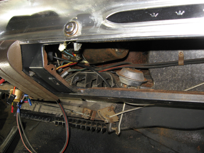
Second, the headpipe was rubbing on the torsion bar. It looks like the headpipe moved a bit when I re-worked the rest of the exhaust.
Third of two problems is the number 8 spark plug lead was dangling loose. That wasn’t an exhaust problem but would certainly contribute to the engine not running well.
OK, new plan: Remove the exhaust manifold, fix the leak, and readjust the headpipe when I put it back together.
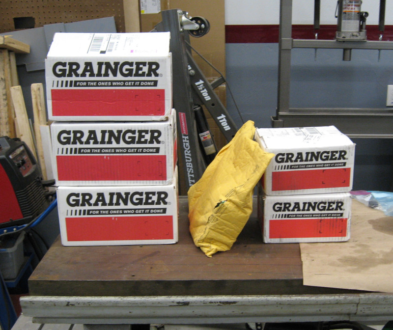
I’ll need new gaskets when I put it back together. Hmm, RockAuto has a closeout special on a FelPro (good brand) exhaust manifold gasket set for $4.58. Order that before they run out!
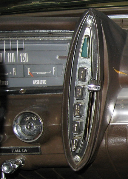
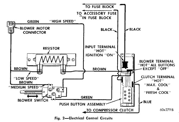
Cars from the 1960’s used a Manifold Heat Control Valve to route hot exhaust gas through the intake manifold to quickly warm it and better vaporize gas in the carburetor. These are spring loaded flapper valves which often get stuck and cause problems. The Manifold Heat Control Valve is important in the winter but not really needed in warm weather.
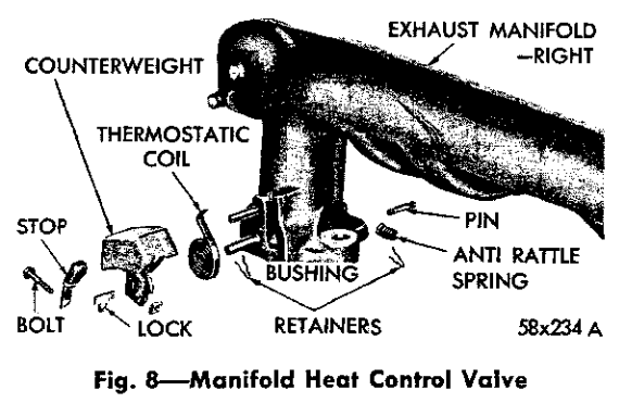
The bushings for the heat control valve were gone, meaning that the valve moved freely but there were large exhaust gas leaks. Since I’m not going to be driving the Imperial much in cold weather a reasonable option is to just remove the whole assembly and plug the holes. Which is exactly what I did!
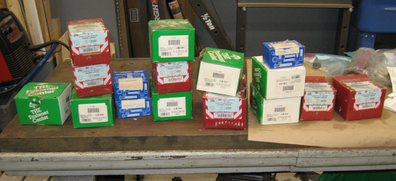
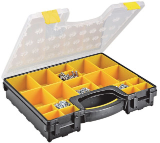
The valve assembly had to be cut out, which actually went smoothly. I measured the holes that were left to determine how much they needed to be drilled out for a bolt – and discovered that they were exactly the right size for a 5/16-24 UNF bolt. As a result of a recent bolt buying spree I “just happened” to have a box of short 5/16-24 UNF bolts. And a 5/16-24 tap. Run a tap through the holes, install the bolts, and the manifold was almost ready to go back on.
Another potential exhaust leak is where the exhaust manifold and headpipe bolt together. If these surfaces aren’t flat a leak can develop – this is a common occurrence in old cars.
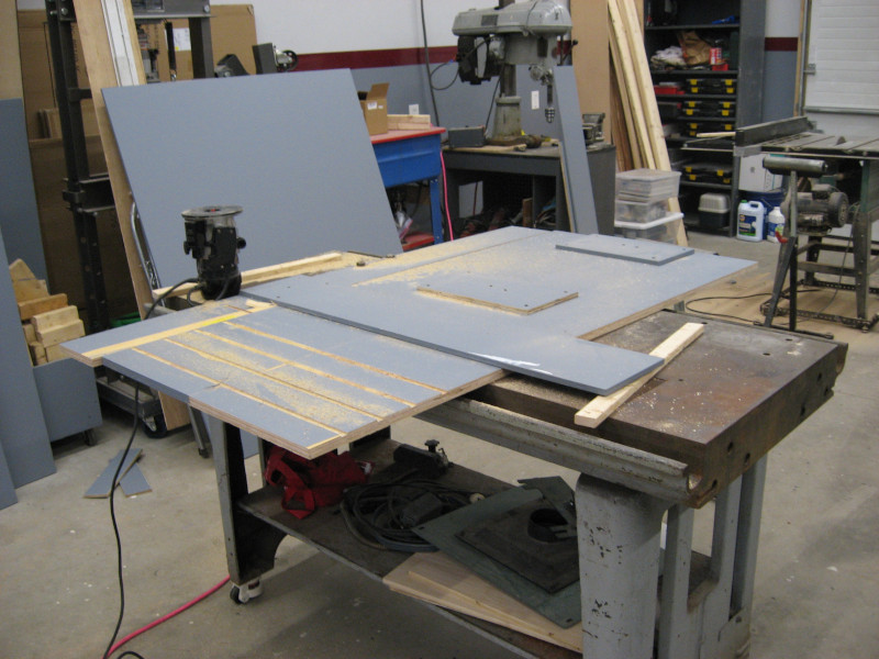
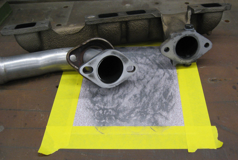
The secret to making exhaust flanges flat is having a flat surface to work with – and my workbench has a machined top that is really flat. Time to tape down some sandpaper so it doesn’t move and start sanding the mating surfaces. When you do this the high point on the flanges become shiny and the low points remain dirty. This lets you clearly see the high and low points, and you continue until the whole surface is uniformly shiny. Or at least close enough…
At this point the flanges on the exhaust manifold and headpipe are flat enough that the gasket will seal.
The next step is to install the exhaust manifold on the car. This involves laying on the fender, holding myself up with one hand, and trying to start the nuts on blind studs underneath the exhaust manifold that I can’t see while balancing everything. It is about as easy as it sounds.
After bolting the manifold to the block the headpipe is loosely installed and adjusted to clear the torsion bar. This remains a tight fit – there is only about 1/4″ clearance between the headpipe and the torsion bar. Hopefully this will be enough. At least there is now positive clearance and not negative clearance. “Negative clearance” is the engineering term for “interference”.
Next: I actually found a New Speedometer Cable! Does it fit?