Its not a workshop without a workbench! Currently the workbench is a plywood top laying on a couple of 44″ tool cabinets which has been waiting for the materials to build a proper workbench. With materials in hand, courtesy of Steel This!, it was time to get going. The inspiration for this project is a Steevo Bench as covered on the Garage Journal website. Yes, this is another bad influence from Garage Journal…
The Drill Press and Welding Cart projects were warm-up for building the workbench. Design goals for the workbench included:
Built around two Harbor Freight 44″ tool cabinets and a Sears 26″ cabinet.
Lower than the current workbench – basically build it as low as possible.
Adjustable feet so the workbench top can be level.
Use the 1″ x 2″ steel tubing also used in other projects.
The two Harbor Freight cabinets were purchased with this project in mind. The Sears cabinet is one I’ve had for about 20 years.
The current workbench – a piece of 1/2″ plywood sitting on top of the Harbor Freight cabinets – is too high and interferes with the electrical outlets. The casters on these cabinets are 7″ tall, so the bench can be lowered up to 7″. The steel tubing frame goes around the cabinets with frame members above and below the cabinet. Using the 1″ x 2″ tubing on its side, the top and bottom pieces add up to 2″. Add another half inch to this for clearance gives 2-1/2″. The leveling feet are made from 5/8 steel plate with a bolt running through it, so the plate plus bolt head is about an inch. This adds up to 3-1/2″, meaning that the workbench top can be dropped over three inches.
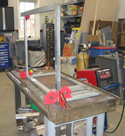
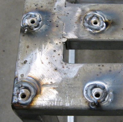
All measurements were checked, double checked, and checked again. And then were test fitted multiple times while building out the bench. Steel tubing was cut to length, fixtured up on the welding table, and welded into place. An overhand was added to the back of the frame to accommodate the lip on the concrete foundation.
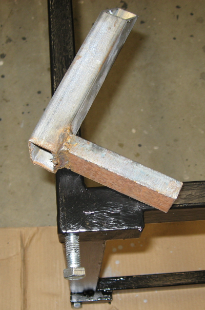
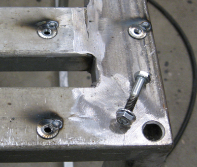
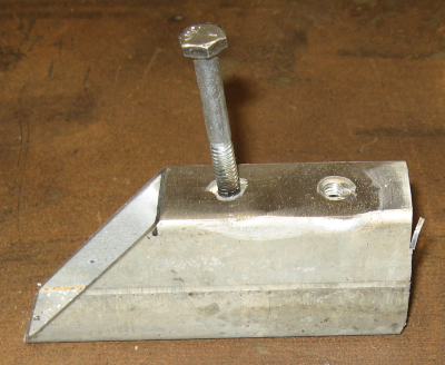
The adjustable feet are made from 1/2″ bolts. I have mentioned the 5/8″ thick steel plate that came with the steel tubing. This was cut into 3″ lengths, drilled and tapped for the 1/2″ bolts, and welded to the bottom of the frame. The bandsaw had no trouble cutting this heavy plate and the drill press made short work of the holes. I’m getting spoiled by a decent fabrication environment!
Adjustable Foot
I was initially concerned about welding these feet on. Welding heavy pieces to thin pieces is difficult. Then I realized that all of the force will be downward – the only times the welds will be stressed at all is when moving the bench around. Which will be done once. When the bench is empty.
Welding guidelines are to focus the heat on the heavy part and watch the puddle. I was pleasantly surprised at how well this worked – I was able to get solid welds with very little blowout on the thinner tubing. Maybe my welding is actually improving!
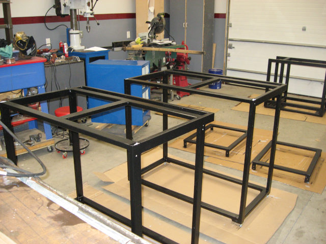
With the frames welded up it was time to paint them. The welding cart was painted at the same time. I was originally going to paint it all black, but decided to paint the file cabinet blue.
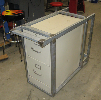
Workbench Frame painted
With the frames completed it was time to move them into position and adjust the feet. All that was left was to slide the tool cabinets into place.
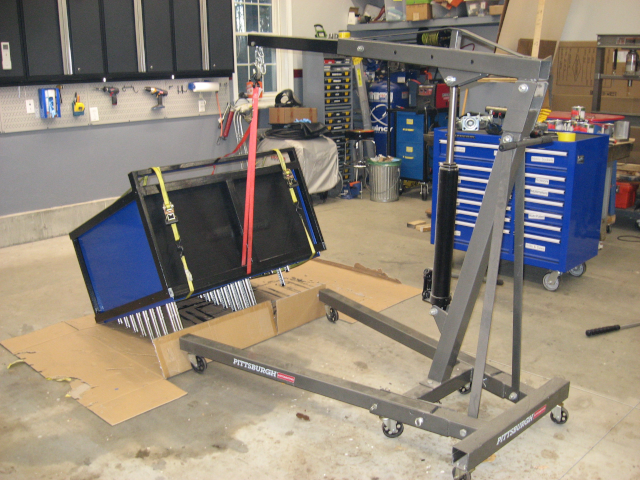
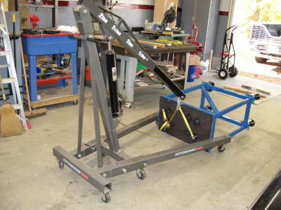
This may have been the most challenging part of the build. The cabinets weigh about 350 lbs. They are loaded with tools, making the actual weight 700-800 lbs. And they are sitting on casters that need to be removed…
First step was to remove all 14 drawers. Then tilt the cabinet over on its face and unbolt the casters. With the tool cabinet still on its face, lay the frame on its face, lift one end of the frame with the engine joist, pick up the other end, and drop the frame over the cabinet. Run some ratchet straps around the frame and cabinet to hold everything together and then tilt frame plus cabinet upright with the engine hoist.
Tilting workbench upright
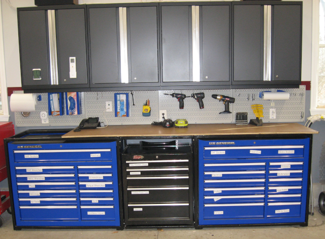
Slide the workbench into place against the wall, check that it is still level, and re-install all 14 drawers. Then repeat the process with the other tool cabinet. With the two sides done the center piece can be bolted into place and the third tool cabinet slid into place.
“Finished” workbench
The old workbench top is being used temporarily. I would like to have a 1/4″ steel top, but steel prices are too high. Maybe next year. For the moment I will add another piece of plywood to cover the entire frame and perhaps cover it with a sheet of rubber. At some point I would also like to replace the Sears cabinet with another Harbor Freight cabinet.
The next project is organizing tools and supplies into the new storage. I may have almost enough space for all my crap! Which clearly means that it is time to start acquiring more tools and supplies…
Next: Construction projects continue in Bandsaw Stand.
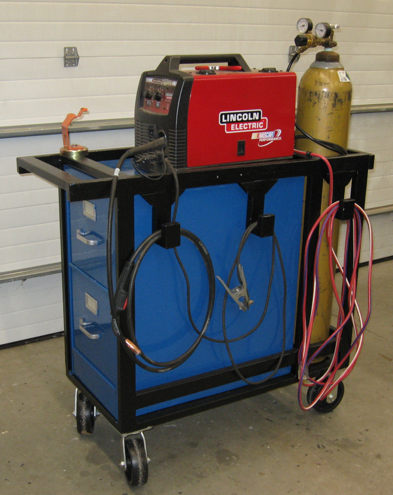
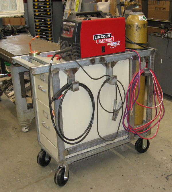
Larger fabrication projects, like the drill press stand chronicled in the previous article How Much Does A “Free” Drill Press Cost?, have been leaving me increasingly dissatisfied with my welding setup. The actual welder, a Lincoln HD140, is fine. The issues are with the cheap Harbor Freight welding cart it is mounted on and the way the various welding equipment and supplies are scattered across multiple locations in the shop.
New welding cart
It should be clear by now that I’m really trying to have the workshop organized and effective for the various jobs I do in it. Part of the madness (please accept the premise that there is a method!) is to use closed storage to keep things clean and organized.
After a few weeks of mulling over various ideas a bit of inspiration struck – what about using a two drawer filing cabinet for storage and building a welding cart around it? Good brands of filing cabinets are durable and can handle heavy loads. One of the drawers is large enough to hold a welding helmet, gloves, and jacket, and the other drawer can be organized with plastic storage containers to hold the various tools, parts, and supplies. New filing cabinets are expensive – at least for the good ones – but used filing cabinets can range from cheap to free.
Nothing cheap enough and close enough showed up on Craig’s List, so I headed over to the local Habitat for Humanity ReStore. They had a number of filing cabinets, including a two drawer Hon for $15. A bit beat up, but the drawers opened and closed smoothly. OK, I’m doing this!
When I got the cabinet home I discovered that I might have been a bit optimistic. The bottom was badly dented and some of the re-enforcing brackets were torn loose. Not a problem – first, this is for a workshop not an office. Second, I have auto body tools and a welder and I’m not afraid to use them! Out came the body hammers and dollies and the filing cabinet became much closer to original. The welder made quick work of re-attaching brackets and frame. I could have added auto body filler and made things perfect – but, “workshop”.
The welding setup includes both the welder and a large gas bottle, so the frame was designed to support both the filing cabinet with welder on top as well as the gas bottle. It was also designed with a handle for pulling it around. I will probably be adding another welder in the future, so the design needed to allow two welders and two gas bottles.
A set of large heavy duty casters were available – the ones from the drill press project that made the drill press too high. That won’t be a problem with the welder. Plus, an easy rolling cart is one of the design goals.
Finally, hangers were needed for the hose going to the MIG gun and ground cable. Since the first thing I have to do when using the welder is grab an extension cord to plug it in I decided to just include an extension cord in the build.
After measuring and making sketches pieces of steel tubing were cut to length, fitted together on the welding table, and welded up. The base was the first thing built: corners were cut at a 45 degree angle and welded together for a finished appearance. Cross beams were welded in place to support the gas bottles and the end of the filing cabinet as well as provide a place to mount the casters.
Base for Welding Cart
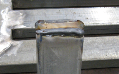
Mitered corners couldn’t be used everywhere. Where the end of a tube would be exposed an end cap was welded in place:
End Cap FittedEnd Cap welded in placeEnd Cap ground smooth
With the base completed the rest of the frame was fitted into place, adjusted, and tack welded:
Fitting up cart frame on welding/fabrication table
After the frame was tack welded, and before doing final welding, the filing cabinet was test fitted:
Test fit of filing cabinet – It fits!
Next up was mounting the casters. On the drill press project I welded 1/4″ steel plates to the bottom of the frame to support the casters. With the welding cart I noticed that the cross braces would fully support the casters. The problem is that the 14 gauge steel tubing is too thin to thread for bolts and welding nuts on the outside of the frame is, to put it mildly, ugly.
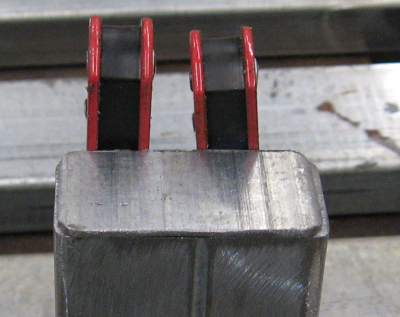
It should be possible to weld an upside down flange nut in place so that the nut is inside the tube. I had been considering various ways to hold a flange nut in place for welding and decided to just make a test piece. It turned out that a step drill would cut exactly the right size hole. Further, if you didn’t run the step drill all the way through the wall of the tubing it would leave a lip that supported the flange nut flush with the outside of the tube!
Flange Nuts tack weldedFlange Nuts welded in placeFlange Nuts welded and ground smooth
The end result is a nut contained inside the tubing. Welding all the way around the nut provides full strength, making this an attractive solution.
I made a template of hole locations from the casters and used it to locate all the mounting holes in the cart frame. After welding all 16 of the flange nuts in place the casters bolted right on.
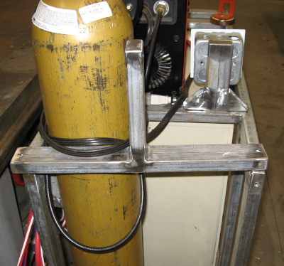
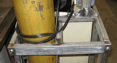
The gas bottles for welding are large, heavy, and dangerous – they hold high pressure gas at 2,000+ psi and weigh 60-80 lbs. You really don’t want them to fall over. They need to be supported at both the top and bottom to make sure they don’t fall over or get out of control. The bottom is easy – just weld in another brace about 2″ off the base.
The top support, on the other hand, can’t be solid. The tanks are too heavy and awkward – not to mention slippery! – to lift five or six feet into the air to clear a top brace. The usual solution is to have a chain that is hooked around the gas tank three or four feet up. Effective but not elegant….
So I designed a removable T brace that would bolt into place using the welded flange nut approach:
T Brace removedT Brace installed
At this point the welding cart was done and ready for paint. Or was it…. Painting makes it difficult to change – I’ve run into this with the drill press where I wanted to change a few things but it is just too much work to remove paint, weld in new pieces, and try to repaint and blend. I decided to use the welding cart for a while and make sure no further changes were needed before painting. This has already proved to be a wise approach!
I tried several approaches before coming up with cable hangers I was happy with. The final design is overkill – each hanger is made of six pieces welded together and bolts to the cart frame using the flange nut approach. This final design is sturdy, doesn’t stick out more than necessary, and can be changed later on if needed – for example, a second welder would add more cables that need to be managed.
Welding Cart
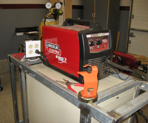
The final bracket supports the quad electrical outlet. As previously mentioned an extension cord is now part of the welding cart allowing the welder to be plugged into it full time. This also provides power for other tools such as lights or grinders. The orange object is a magnetic holder for the MIG gun – it is easy to grab it and stick it on the welding table or whatever I’m working on to provide a handy place to secure the MIG gun.
Welding Cart Electrical
At this point the welding cart is “done”. I’ve used it a few times and it is a definite improvement over the previous cart – it is much stronger, better organized, has the storage I need, and is (hopefully) future resistant. I really like being able to easily drag it where needed and grab the welding helmet, gloves, and jacket directly out of the cart – and then put everything back up when the job is done! It is also nice being able to find the various tools, accessories, and supplies.
Some big fabrication projects are coming up in the near future – it will be interesting to discover if any further changes or modifications are needed! The cart will ultimately be painted – probably when it is time to paint the next project.
Update:
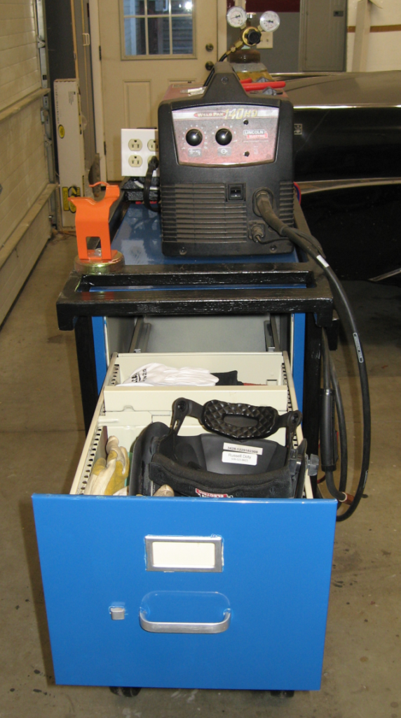
After using the cart I decided no changes were needed so I went ahead and painted it. It is working out well – I especially like being able to plug it in (with the included extension cord) and grab the welding helmet and gloves out of the top drawer.
Welding cart drawers
Next: keep the building trend going with a Workbench.
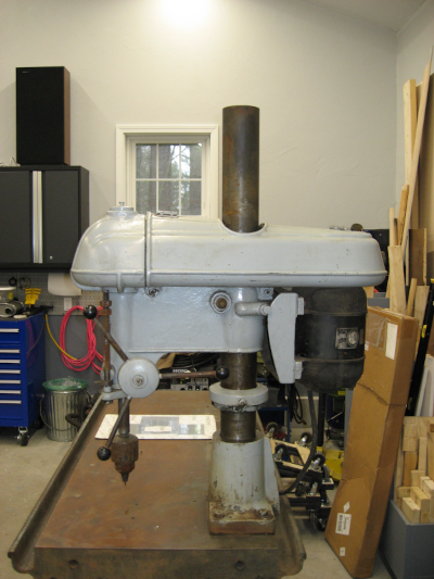
Searching Craigs List for a welding table a couple of years ago I stumbled across a triple drill press mounted on a heavy machine tool base. This machine tool base was 30″ x 60″, made of heavy steel (4″ thick at the ends), with a machined flat top surface – perfect for a heavy duty welding and fabrication table! I negotiated what I thought was a reasonable price and was told that for that price I could only have one of the drill presses. I hadn’t planned on taking any of the drill presses, but I checked them out and decided to take the best one.
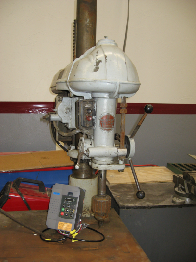
Drill Press mounted on welding/fabrication table
This drill press is an older Walker Turner industrial 1hp drill press which was designed to be run all day every day making large holes in heavy steel parts. Readily available consumer grade drill presses are designed for wood and run at high rpm and low torque. Metal drill presses like this Walker Turner run at low speed and high torque. It weighs around 300 lbs and requires three phase power.
First concern: does it work and is it worth saving? Everything moved smoothly without strange grinding noises, so it wasn’t rusted up. I put a dial indicator on the spindle and observed less than 0.003″ of runout – not great, but entirely usable. The motor requires 3 phase power, which is used in factories for high power electric motors. Homes only have single phase power, which is a problem. Fortunately there is a solution for this – a VFD, or Variable Frequency Drive, which converts single phase power into 3 phase power and also provides speed control.
A VFD was ordered and temporarily installed:
VFD temporarily installed
Fingers crossed it was plugged in and turned on… And worked perfectly! A bit of noise, but not bad. Incredible torque at low rpm – I couldn’t stall with anything I tried. This monster still has years of use left in it.
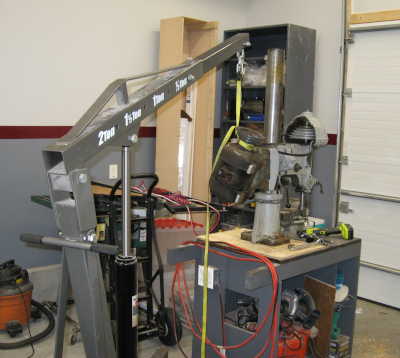
It couldn’t stay on the welding/fabrication table – not while using it as a table. So it came off and was temporarily mounted on a wooden cart while I started searching for parts to build a proper stand for it. The engine hoist was invaluable for handling the pieces – even broken down into three major subassemblies the parts were too heavy for me to lift!
Drill Press temporary installation
The first thing needed was a base to bolt the drill press to. I was looking for a 12″x18″ or 18″x24″ plate of 1/2″ steel. As mentioned other places steel is extremely expensive at the moment so I wanted a cheap used piece. After several months of searching an 18″x30″ piece of 1″ steel plate showed up on Craigs List. Complete overkill, so $140 later it was mine.
Next need was steel tubing for the frame. Perhaps something like what was described in the previous post…
Three elements drove the design of the drill press stand: the drill press itself, the base plate, and an existing tool box that I wanted to incorporate into the stand for storage. With all raw materials in place and a design roughed out it was time to start building!
Since multiple projects are planned a better way to cut the steel tubing to length was needed. Harbor Freight put their horizontal bandsaw on sale – the perfect tool for this task – so another power tool was added to the workshop.
The frame was fairly simple – a box with casters on the bottom and the 1″ steel plate on the top. Measure, cut, tack weld, test fit, adjust, full weld, grind, and the frame was ready to go.
Drill Press Frame ready for paint
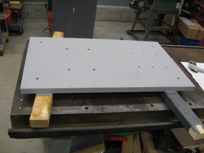
The base plate needed many large holes which were measured and marked for drilling. The ~200 lb plate was wrestled onto the temporary cart and the Walker Turner fired up for its first real job. How did it work? Like the proverbial hot knife through butter. Not only did the drill press not strain when drilling 1/2″ holes through 1″ steel plate, it didn’t seem to even notice!
Well, not exactly 1/2″ holes… To be precise, 27/64″ holes which were then threaded with a 1/2″ – 11 tap for 1/2″ bolts. Half a dozen 3/8″ holes were drilled and tapped to secure a vise – planning ahead.
Steel Plate with holes drilled and tapped
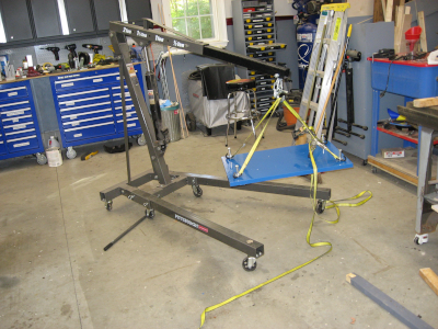
After painting the base plate was turned face down on the floor, the stand was placed on top, and the stand secured to the base plate with four 1/2″ bolts, The trusty engine hoist was then used to flip the drill press stand up on its casters.
Lifting 200 lb steel plateDrill Press Stand ready to flip upright
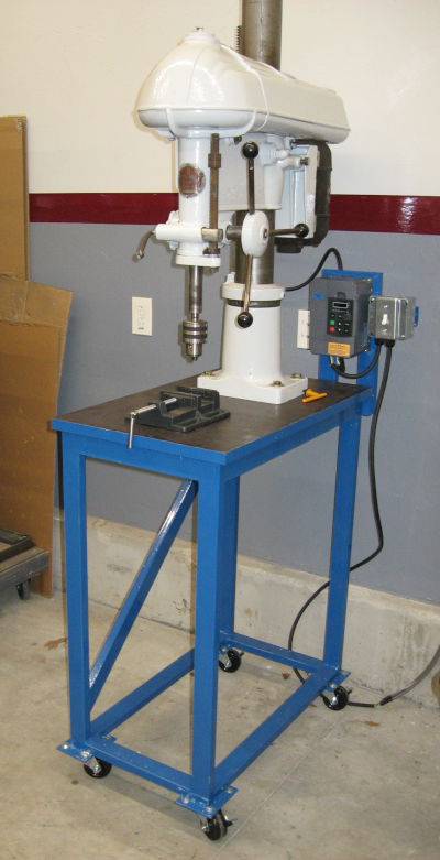
With heavy drilling over for the time being, the drill press was removed from the temporary cart. It was cleaned and painted before being installed on its final home. A bracket was added for the VFD and final wiring was done. Two years after buying it the Walker Turner is ready for “production” use!
Walker Turner Drill Press
Those with sharp eyes may notice that the base of the drill press is empty… The tool boxes will be moved in as part of an upcoming workshop cleanup and re-organization. Those same sharp eyes may also notice that the casters look different. The original casters were too tall and were replaced with smaller casters.
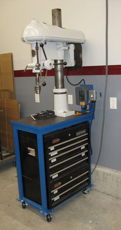
Update: Here is the drill press with the tool chests installed and loaded up with drilling accessories:
$350 Horizontal Band Saw (purchased for this project)
$150 Drill Bits and Taps
$60 Drill Chuck and accessories
$45 Paint and supplies
$60 Electrical Wiring
$50 Consumables (grinding, etc.)
$296 Mileage @ $0.52/mile
Total: $1906
Out of Pocket
Only count the out of pocket expenses directly used on the drill press. Tools that are used on other projects are considered part of general shop overhead.
$0 Drill Press (included at no charge with welding/fabrication table)
$85 VFD
$140 Steel plate
$40 Steel tubing (amount actually used for drill press stand)
$60 Drill Chuck and accessories
$30 Paint and supplies (amount actually used for drill press stand)
$20 Electrical wiring (amount actually used for drill press stand)
Total: $375
Looking at what was actually spent on the drill press I’m going to say that this “free” drill press cost about $400 to get to a finished and ready to use state. Very reasonable for the capabilities of this machine!
Several workshop projects have been on hold due to the high price of steel. In late 2019 a 24′ piece of 1″ x 2″ 11 gauge steel tubing was $65. In early 2020 prices started climbing – today that same piece of steel tubing is $156! A 5′ x 10′ sheet of 1/4″ steel plate has gone from $413 to $1240. Ouch.
Even worse, steel prices show no sign of declining. Steel is in short supply and prices continue to go up, with corrections not predicted until 2022 or 2023.
I’ve been keeping an eye on CraigsList for the last year but haven’t seen anything. Then a listing appeared for some 7′ long pieces of 14 gauge 1″ x 2″ tubing for $8 each. Hmm, this is about half of 2019 prices and one eighth of today’s prices – worth checking out! A little bit lighter than originally planned, but still plenty strong enough for my needs. I believe I’ve mentioned my propensity for overkill? 7′ long pieces will work for my applications and are much easier to handle than 24′. Running some quick math said that 26 pieces would cover all of the projects I have planned.
The seller was in New Hampshire, so I arranged a time and hopped into the pickup. The material was as advertised so I took it. The deal was for 26 pieces for $220. He had a pile of 40 pieces – mostly the full 7′ lengths but a number of shorter pieces. While we were loading the tubing he decided “oh, just take the whole pile”. Score!
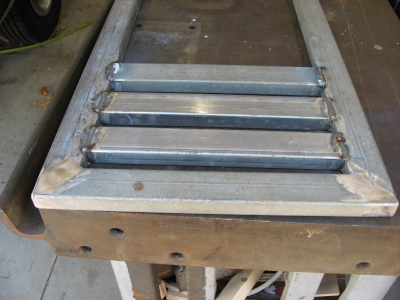
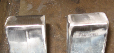
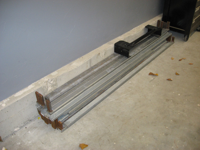
I now have 250’+ of steel tubing which should cover all planned projects. Stay tuned for details!
Steel tubing for projects
Those fingers sticking up from the ends of the tubing? Those are a bonus – they are 2″ wide pieces of 5/8″ thick steel. I’ve got plans for how to use them in various projects…
After fixing the latest electrical gremlin in Electrical 12: Dash It All! it was time for something completely different.
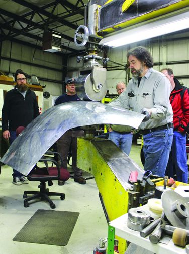
I attended a four day intensive course on coachbuilding taught by Wray Schelin of ProShaper. What is coachbuilding, you ask? Good question! Coachbuilders build custom bodies for cars – think of custom Bugattis from the 1930’s or the handbuilt Ferraris and Jaguars from the 1940’s and 1950’s. These cars were handbuilt and either unique or low volume production.
Wray Schelin forming a custom body panel on an english wheel
Coachbuilding is the process – actually, the art – of transforming flat sheets of metal into complex and beautiful shapes. Also precise and functional shapes – the end result is a vehicle that has doors, windows, hoods, bonnets, boots, chassis, drivetrain, and fuel. It must go down the road while carrying people while also being art.
Metal Shaping uses a variety of tools and techniques to form metal. Surprisingly, very complex shapes can be created with a few simple tools. The starting point is often simply beating the metal with a variety of hammers. Next the parts are smoothed and refined on an english wheel. Edges are formed with a tipping wheel. Parts are cut to size with hand snips and precision fit with a hand grinder. Finally the parts are welded into place with a TIG welder.
All the tools needed to customize a car – or even build a complete body from scratch! – can be purchased for less than $2,000. Of course you can spend much more, but you don’t have to. Final results depend more on the skill of the coachbuilder than the size of the shop. Some Italian coachbuilders produced beautiful results with nothing more than a shed, a tree stump to beat on, an assortment of hammers, and a gas welder!
There were seven people in the class I took: a husband and wife from Florida, two people from California, one from Tennesee, and one from New Jersey. I was the only person from Massachussetts in the class. Everyone was interested in everyone else’s projects, so I was compelled to bring my Imperial to class on the second day.
I didn’t work on the Imperial in class but did get some expert advice on how to proceed with rust repairs. I will tackle the rust and dent repairs this winter – will provide updates as I abuse the metal.
The class itself was almost brutal – 9:00am to 10:00pm for four days straight. After the first day everything was hands on working on projects. Since I am an out of shape slug I was completely wiped out at the end of each day…
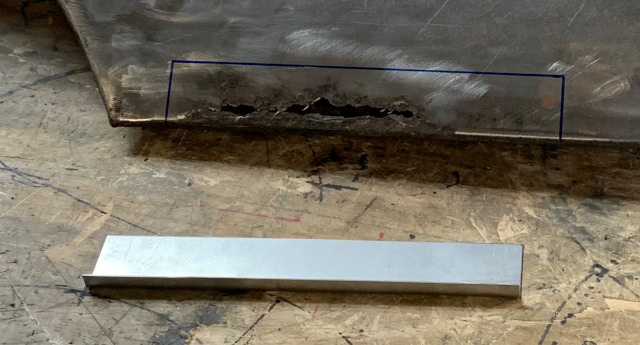
I worked on two projects in class. One was to help a classmate make a replacement aluminum skin for the trunk lid of a 1964 Alfa Romeo GTV. He had shipped in a mangled trunk lid from an aluminum racing car and wanted to repair the damaged frame and replace the skin. The other class project was to restore the front fender from a Jaguar E-type. It had rust damage and a dent, two of the most common problems in restoration.
The Alfa trunk skin required making a flexible shape pattern from the original trunk lid and creating the compound contours on an english wheel. The trunk lid curves both side to side and front to back – ideal for the english wheel. We were able to shape the skin in class but ran out of time working on repairing the frame – someone had cut large chunks out of the frame that had to be recreated from scratch.
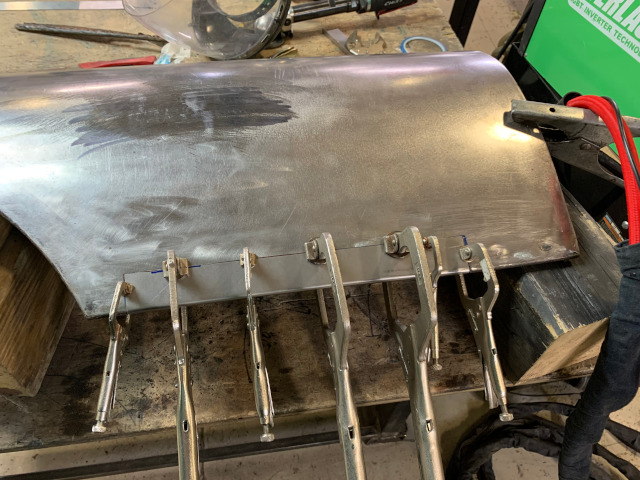
Rust repair involves creating a patch panel that matches the curves of the car, cutting out the damaged area, fitting the patch panel to the newly created hole, welding the patch panel into place, and finishing off the welds.
After instructions on how to create and fit a patch panel I had the tightest fit of any patch panel I have ever made. Wray looked at it and said “it needs to be tighter but we can fix it up in finishing”. Ouch. The next one will be better!
Welding was done with TIG, rather than the MIG welder I’m used to using. The weld beads were much smaller that those produced by MIG, reducing the need for grinding. The TIG welds also grind easier than MIG, further reducing the need for grinding.
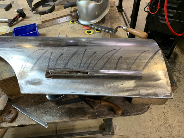
Welding causes the metal to shrink which introduces deformations in the rest of the panel – commonly bends or waves. Planishing is a process of pounding on the weld with a hammer and dolly to slightly stretch the metal and return it to its original shape. This is the first time someone has taught me how to planish. After working on the Jaguar panel I tried making a simple patch panel from two pieces of scrap. After TIG welding it together it was bowed across the weld. Planishing with hammer and dolly quickly straightened it back out – this technique actually works!
Jaguar Fender showing rust along with patch panelRust cut out, patch panel fitted, clamped, ready for weldingWelded, planished, and finished. Cut-out rusted piece for comparison.
Dent repair is a four step process. First you identify high and low spots by darkening the surface with marker fluid and sanding with a flat block – this leaves the high spots shiny and the low spots dark. Then you bring up the low areas using a dolly and a slapper or slapping spoon. Third you bring down the high areas by heating, either with a torch or by using a shrinking disc. Wray recommends using the shrinking disc since it selectively heats the high areas and reduces them. Fourth is to repeat the first three steps until you have a perfect surface.
This is a lot of work but the results are beautiful.
I learned a lot in the class. As usual, the challenge will be to apply these lessons before I forget them. Now to see if I can get a TIG welder for Christmas…
A few weeks ago I went to dinner in the Imperial. It was dark by the time we left, making this the first time to drive the car after dark. To my surprise I had no dash lights! Making matters worse the headlights were aimed sharply down, giving me about five feet of visibility (slight exaggeration). Good thing that it was a fairly short drive home on roads I knew well!
When the instrument panel was rebuilt the dash lights worked fine, so this was completely unexpected. I hadn’t done anything to the instrument panel!
Or had I…
When working on the HVAC controls I had discovered that the lighting panel was unplugged. So I plugged it in and it glowed. One problem solved! Or was it “one problem solved?”?
The most common failure mode on electroluminescent lighting is for the power pack to get weak, causing the dash lights to get dimmer and dimmer. The power pack produces 200 volts of alternating current. The capacitors in these power packs dry out over time, and the driver transistor can fail. The extra load of the HVAC panel could be enough to kill the lights.
Fortunately there are companies who rebuild the lighting power packs. Unfortunately this is fairly expensive and takes months. Even worse is the difficulty getting to the power pack: it is mounted high up on on the drivers side sidewall behind the kick panel. It is completely buried behind wiring, control cables, the emergency brake assembly, and the huge brake pedal bracket. It is a major effort to contort yourself under the dash to be able to even see part of it – I have no idea how to actually get it out! And back in… I suspect that this power pack was the very first thing installed inside the car and everything else was built around it.
There are some people making new replacement power packs – compatible modules made with new technology. These cost about half as much as a rebuilt original module and claim to work better. So I took a chance and ordered one from Ebay. If this didn’t work I could always pull the original power pack and have it rebuilt. Assuming I could figure out how to remove and re-install the old one…
When the new module showed up the first step was to test it. I unplugged the wiring from the old power pack and plugged it into the new module – fortunately the wiring was relatively accessible. Time to double check connections, turn off workshop lights, and turn on the headlights.
The instrument panel remained dark.
Not unexpected, so turn the dimmer control. And there was light! The instrument cluster illuminated just as it was supposed to. “And there was much rejoicing”.
With the new module working it was time to mount it. The new module is much smaller than the original, so there was no point in trying to mount it in the same place. There was plenty of space on the side panel for the new module, so it was simply a matter of choosing a location and drilling a hole for the mounting screws.
Hmm, while in there I might as well add some soundproofing. I had saved the larger scraps of Noico sound deadening material and used these to cover most of the sidewall. After this it was simply a matter of installing the new driver module, connecting it, checking that the instrument panel lights still worked, and re-installing the kick panel. One task down!
The headlight problem was simple. I had replaced original rear springs with heavy duty springs which raised the rear end. Raising the rear end makes the headlights point down. Fortunately headlights are adjustable: remove three screws in the headlight trim ring, turn the vertical adjustment screw until they are the proper height, and then reinstall the trim ring.
Now I just need to get out at night and check everything out!
Update
I got out at night and everything worked. Not quite as bright as I would like but usable.
After (finally!) getting the alternator and voltage regulator straightened out in Electrical 10: 2 Bad let’s look at some of the tools and techniques used.
My approach to making electrical connections has evolved significantly. This will be familiar to many people – most of them will know more about wiring than I do!
The early days
For many years these were my preferred tools.
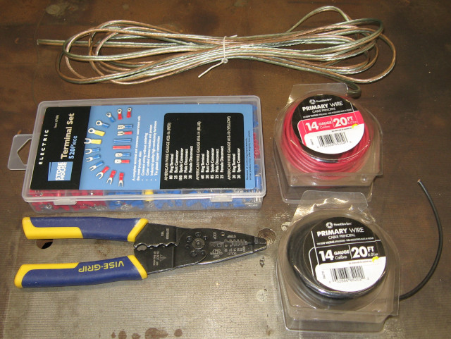
Stripper/Crimper, cheap terminals, primary wire and lamp cord/zip cord
The only wire I knew was primary wire or hookup wire, purchased at a high price in short rolls from big box stores, or lamp cord. A cheap pair of pliers style tools served to both strip wire and crimp connectors. And the connectors were purchased in convenient cheap assortments.
The wiring pliers were a nuisance for stripping wire – it was far more difficult to get a good strip than it should have been. Also, it was difficult to get good crimps with them. The cheap crimp connectors were light weight and in many cases marginal. The plastic was badly crushed getting a crimp – and you couldn’t tell if you got a good crimp. And they simply looked cheap! Just looking at wiring done with these tools made you think it was a hack job. Often because it was a hack job!
Insulated Butt Connector
Despite all this, these were my tools for forty years.
The Transition
The combination of the Imperial restoration and a dedicated workshop has lead to a dramatic upgrade in my tools. It has also lead me to learn more about what tools and techniques are available, resulting in significant improvements in my knowledge and skill in many areas. I’m not going to claim to be good, but I will claim to be less bad!
One of the first things electrical I learned about was heat shrink connectors. The cheap connectors I was familiar with did a poor job of sealing, and the only thing holding the connection together was the (often poor) mechanical crimp. The heat shrink connectors were more expensive, but provided a much better seal, a better mechanical connection, and a more professional appearance. But you were still crushing the plastic to make a crimp.
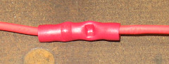
Heat Shrink Butt Connector, as crimped and shrunk
Revelation
The real revelation came when I read the Bodenzord blog series of articles on DIY Bussmann RTMR Fuse Block. This introduced me to a new world of parts, tools, techniques, and sources for materials: GXL automotive wire, Weatherpack and Metri-Pack sealed connectors, Bussmann fuse blocks, real crimpers and automatic wire strippers. The credit card came out and I’ve never looked back!
Terminals
I’ve spent a lot of time talking about corrosion in automotive wiring. The car companies addressed this 30 years ago with sealed connectors which dramatically improved electrical reliability. These connectors have water tight male and female housings, rubber gaskets between the male and female housings, and rubber seals where the wires go into the housings. If water can’t get in it won’t corrode! The connectors crimp both to the bare end of the wire as well as to the insulation, providing a more secure connection.
There are many different styles, but the Bodenzord article recommended the Weatherpack and Metri-Pack connectors which have been widely used on many US cars and which are available at “reasonable” cost. You can get them online from industrial distributors such as Waytek, from Amazon, and from Ebay. You have to be careful with Amazon and Ebay as they are filled with cheap knockoffs, so I mainly use Waytek.
The Metri-Pack 280 series is especially versatile as the female connectors can be directly used with mini-ATA fuses and micro relays. Among other applications, the Bussmann 15XXX series fuse blocks are directly wired with Metri-Pack 280 connectors. This makes it easy to build complex electrical systems. Metri-Pack 280 can handle up to 30 amps of power.
Metri-Pack 280 requires many components: both male and female terminals for various gauges of wire as well as male and female shells and retainer clips for different numbers of terminals. One, two, three, and four terminal shells will cover most uses. You will also need sealing rings for various gauges of wire.
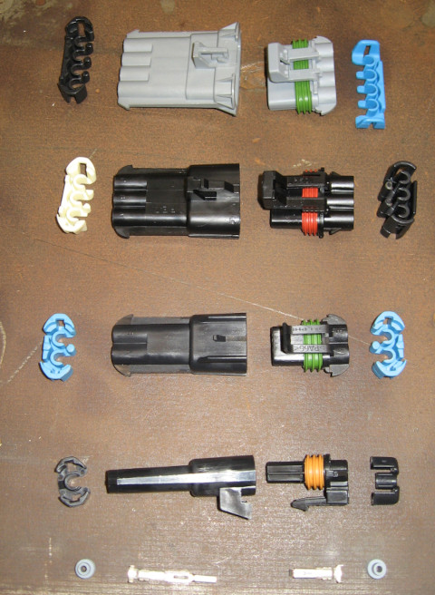
Metri-Pack 280 connectors, 1-4 terminal. Terminal pins and seals at bottom.
Metri-Pack can quickly get expensive. I decided to build out a custom kit using parts from Waytek as they have some of the best prices for quantity purchases. Waytek has minimum quantities for many of their parts; this can make life a bit complicated when putting together an order. For some parts, like Female Tangless Terminals for 12-14ga wire (used in mass quantities with Bussmann fuse blocks) you really want to order 100-200 at a time. Wiring a single Bussmann fuse box will use 40+ connectors – plus the number consumed for changes and mistakes… Since you will generally have a connector on each end of each wire the numbers quickly add up.
For other parts, like 4 terminal shells, it is difficult to justify ordering 25 at a time. In any case, when assembling a custom kit for working with Metri-Pack 280 it is more cost effective to order what you need than to buy one of the pre-packaged kits.
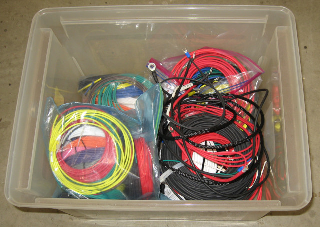
Wire
With connectors chosen, what wire to use with them? Car companies specify GXL and TXL wire because the insulation handles high heat, is oil resistant, and resists mechanical abrasion. TXL has thinner insulation and is more flexible while GXL is tougher. I’ve standardized on GXL.
GXL is hard to find and expensive – unless you go online. Even then you are often looking at 500’ or 1,000’ rolls – this gets expensive really fast when you want to put together a foundation of colors and wire size. For working on automotive electrical harnesses in is reasonable to have 6-10 colors of wire in multiple gauges. Do the math and you are quickly looking at 30+ rolls of wire!
Fortunately there is Wire Barn who offer packages of 25’ rolls of GXL wire in 6, 8, 10, or 11 different colors and in sizes ranging from 8ga to 20ga. Multi packs in 12ga, 14ga, and 16ga provide a great starting point for repair work and building wire harnesses. As you use them up you can either replace the colors you use or just buy another multi pack. Add some 100’ rolls in red and black in 10ga, 12ga, and 14ga and you are ready for just about anything.
Wire Box: GXL wire in 18GA to 10GA
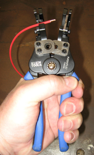
Wiring Tools
I bought a pair of Klein automatic wire strippers to try out. Ten minutes into my first wiring project using these I was asking “why didn’t I get these 30 years ago?!?” Stick the wire in the tool, squeeze, and you have a perfect strip every time. Strongly recommended!
Automatic Wire Strippers
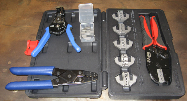
Looking into better crimpers I discovered ratchet crimpers. These do a better job of crimping and are more reliable and consistent than pliers style crimpers. Ratchet crimpers are available as frames which hold a variety of crimping dies – which means that you actually have the proper tool for each type of terminal you are crimping! Many different models are available at different price points.
Ratchet Crimper with dies, Automatic Wire Stripper, and WeatherPack Crimper
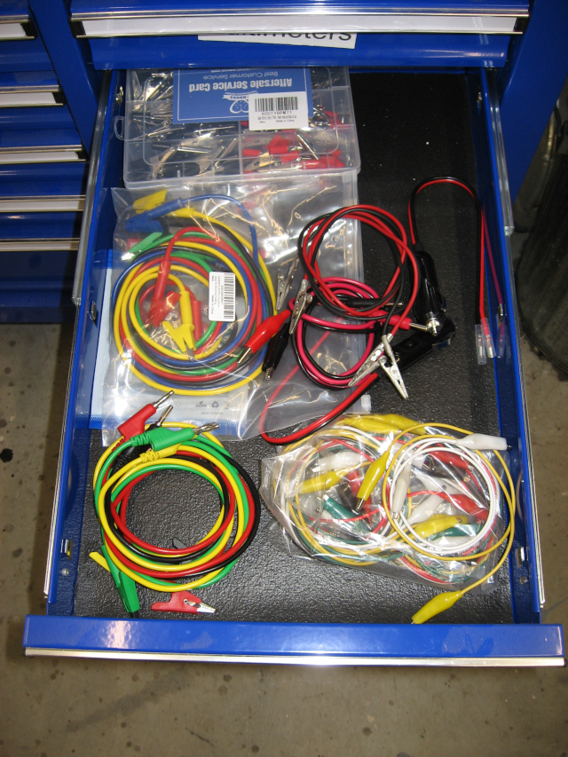
Multimeter
You absolutely have to have a multimeter for working on cars. After years with cheap multimeters I finally treated myself to a decent automotive meter – an Actron CP7677. In addition to the usual volts, resistance, and current, this meter also measures RPM and dwell angle.
The best addition to a multimeter is a good assortment of Test Leads -or perhaps an assortment of good test leads – with probes, clamps, extensions, and alligator clips. Also valuable are jumpers and extensions which allow you to temporarily connect circuits.
Multimeter with test leadsAssorted test leads and jumpers
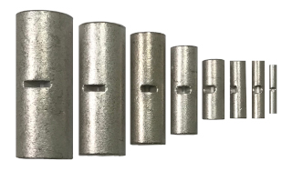
Non-Insulated Connectors
At this point I was happy with the Weatherpack and Metri-Pack terminals but still didn’t like the insulated butt connectors and ring connectors – not even the heat shrink versions. I had read recommendations for non-insulated connectors so I decided to try them.
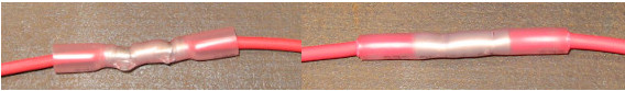
Non-Insulated Butt Connectors for different gauges of wire
Non insulated connectors crimp better than insulated – with no chance of damaging the insulation – so this is a good starting point. After crimping you cover them with heat shrink tubing. Even better, cover them with marine heat shrink tubing, which is lined with an adhesive that melts and bonds to the wire for a water-tight seal. Marine heat shrink tubing is available in different colors, allowing you to match it to the wire. The end result is less bulky than insulated connectors and has a more professional look.
After using them for a while I’m sold on non-insulated connectors. About the only place I’m now using insulated connectors is for quick and dirty temporary jobs like building a test harness. You will be totally shocked that the best place I’ve found for high quality non-insulated connectors in reasonable quantities is Waytek…
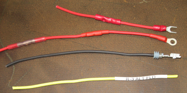
Crimp Connectors
Top: Insulated butt connector and insulated spade connector.
Middle (red): from left: insulated heat shrink connector, non-insulated butt connector with red marine heat shrink tubing, and non-insulated ring connector with red marine heat shrink tubing.
Middle (black): Metri-Pack 280 female connector with ring seal.
Bottom: heat shrink label.
Final Thoughts
While it has involved an investment it tools, connectors, and wire, I’m much happier with the results of my current wiring efforts. Using these tools and techniques produces wiring that is more reliable, has higher capacity, and is easier to work on than what shipped from the factory 60 years ago. In the past I was actually somewhat embarrassed about how my wiring jobs looked. Now I’m rather proud of how the Imperial is turning out. Even better, I’m no longer afraid to tackle new wiring or to troubleshoot electrical problems!
With First Cruise Night! under my belt it was time for the next adventure. One of the classic excuses for driving a classic car is to go get ice cream.
Saturday (yesterday) was a beautiful day so she who must be obeyed and I headed out in the Imperial for some dairy ecstasy.
We have a great local ice cream shop – Kimball Farm – who make their own incredible ice cream. They also have a Grill Shack that does a great job with fried clams, fried shrimp, onion rings and lobster rolls.
Kimball Farm in Lancaster, MA
A 15 mile drive on back roads through some small New England towns and we were at the Site of Happiness. We had to wait in line about 20 minutes – not surprising for Labor Day weekend. I had a Kiddie Cup (what most places call a large serving…) of coconut almond chocolate chip.
Great weather, a nice drive, and fantastic ice cream – definitely the makings of a good day!
This wasn’t our first trip to Kimball Farm – by far! – but was the first in the Imperial.
Despite some of the issues covered in the previous article Electrical 10: 2 Bad the Imperial was drivable – so time to drive it!
One of the reasons for getting the Imperial was to participate in car related events like Cruise Nights. With the Imperial running the first planned event was the local Thursday Night Cruzzin’ at Hebert’s Candy Mansion. I’ve been trying to do this since May – but every Thursday either we were traveling, it was raining, or I had started another project on the Imperial and was waiting for parts and couldn’t drive it. It seems like it has rained every Thursday night this entire summer.
Today it finally happened.
Thursday Night Cruizzin’ at Heberts Candy Mansion in Shrewsbury, MA
It wasn’t raining, so they didn’t cancel the event. The alternator still isn’t straightened out, but a short drive won’t hurt anything. The temperature was 93 degrees, so pack a bottle of water. I’m going!
15-20 cars showed up, ranging from new sports cars to 1920’s-1930’s cars – mostly 1960’s and 1970’s cars. I’m in the right demographic – many of the people there were even older than me. There were several families with kids, which is always good to see.
I had the chance to talk to several people, including some who were very knowledgeable about Mopar’s. I spent at least a half hour talking to a father and son who own a restoration shop specializing in Forward Look Chryslers – a range of Chryslers from the mid 50’s to mid 60’s. In fact they have restored a number of Imperials like mine! They have a high end restoration shop, with some of their recent projects costing over $600,000. I’m probably not taking my car there…
But I did get some good insights from them, especially around paint and chrome. Tom suggested that painting the hood and trunk lid and giving the car a good buff and polish would make it presentable.
All in all a fun evening!
And, of course, the weather forecast for next Thursday is rain…
In the last article Electrical 9: Up Gauging we largely finished upgrading the Imperial wiring. But the story wasn’t done. Bypassing the ammeter leaves no way to know the state of the charging system, so I planned to add a voltmeter.
This led to buying a <$20 multifunction digital gauge that included a clock, inside and outside temperature, and a voltmeter. Trying this out on a test drive produced immediate concern – the voltmeter said 12.3V when the system should have been over 13 volts. This indicated that the system isn’t charging, and driving the car would just run down the battery. A deeper dive was clearly called for.
Time to grab the good multimeter and connect it to the battery. This showed 12.7V, a reasonable value. The cheap, straight from the Far East multifunction device was inaccurate – shocking! The next step was to fire up the engine. If the charging system was working the voltage at the battery should jump to 13.2-13.4V. With the engine running the voltage stayed absolutely flat – no change at all. Krud. The charging system was actually bad.
Three things could be bad: the voltage regulator, the alternator, or the wiring. And they were all new. In fact, the voltage regulator was an upgraded solid state regulator that should work better than the old electro-mechanical regulator.
Still, the symptoms looked like a voltage regulator. The fastest way to get a new one was through Amazon, so an order was placed. I still needed a voltmeter, so I also ordered a dual USB with voltmeter that plugs into the cigar lighter. The new regulator arrived, was installed, and no change. The new voltmeter seemed accurate when compared to the digital multimeter.
Again, krud. OK, check the alternator wiring against the service manual again. There are only three wires and it is straightforward; everything looks correct. OK, that leaves the alternator. While getting ready to order another new alternator (the alternator was replaced during the rebuild) I remembered that I had saved the old alternator. I was even able to find it. OK, install the old 35 amp alternator, verify that it works, and then order another 65 amp alternator.
Fire up the engine – and no change. Still no charging. Krud. The possibilities are two bad voltage regulators, two bad alternators, or bad wiring. I spent a couple of days checking everything – tracing the wiring, checking the wiring, jumpering around the wiring with direct connections, running various tests, and in general pounding my head against a brick wall.
While reading up on charging system tests for the 87th time I realized that I had done an alternator test wrong. The test is to connect the FLD (Field) terminal on the alternator directly to the positive post of the battery. If the alternator is good it will over-charge the battery, producing over 14V. You don’t want to do this for long, as it will destroy the battery and the alternator.
When I performed this test the first time I had left the wiring harness connected. This acted like a dead short, producing sparks and instantly heating my test wire. Thinking about it, this shouldn’t have happened. This time I disconnected the wiring harness from the alternator, connected a test wire, and started the engine.
With considerable fear I touched the test wire to the positive post of the battery – and nothing dramatic happened! OK, a good sign. Hold the test wire on the battery terminal and the voltage reading starts going up, quickly exceeding 13.6V and clearly charging the battery. Now this is a very good sign! It shows that the alternator is good, strongly suggests that the wiring is correct, and points a finger at the voltage regulator.
Next question: is the new 60 amp alternator also good? Time to re-install the new alternator and re-run the test. With the new more powerful alternator the voltage quickly exceeded 14V. With the alternator good and the wiring good, pretty much the only thing left is the voltage regulator.
Two bad voltage regulators? Shouldn’t happen. For the third voltage regulator I ordered a premium regulator from RockAuto. More expensive, but hopefully better quality.
When the third voltage regulator arrived I bench tested it with a regulated power supply. Unlike the other two voltage regulators, this one showed 12V on the output FLD terminal; the others showed 0V in this test. An encouraging sign, so time to install this regulator.
With the third voltage regulator installed I once again fired up the engine – and watched the digital multimeter rise to 13.3V! The charging system is working. And the USB/voltmeter in the cigar lighter is also showing 13.3V.
The only thing left was to confirm these results. The voltmeter showed a consistent 13.3-13.4V during a test drive, exactly what it should be.
This one had me tearing my hair out. I don’t expect to get two bad parts in a row – I don’t “expect” to get one bad part in a row! I learned more about testing alternators and voltage regulators, so should be able to figure out something like this much faster in the future. Another lesson is to order parts from reputable sources.
With the charging system working I can call the electrical upgrades done.
Update 1:
The next morning I headed out on a longer test drive. Immediately after starting the voltage went to 15.3V and the voltmeter started saying “tilt”. Not good – this looks like the voltage regulator is shorted out. Pulled the car back into the garage, hooked up the good multimeter, and it was reading 15.6V at idle. Since this will fry the battery, the alternator, and what is left of the voltage regulator I started troubleshooting the charging system (again).
The voltage then went to battery voltage, like it was before I installed this new regulator. I checked across the IGN and FLD terminals and it showed an open circuit. The regulator is dead.
What is going on here??? Three bad voltage regulators? Mentally going through everything I had done I began to question how I tested this regulator. I had hooked it up to a bench power supply which could have put up to 10 amps through the regulator. In fact, this was likely – one of the resistors on the voltage regulator got so hot from the test that I burned my hand when I picked it up. Could I have almost burned out the regulator, leaving it good enough to work initially but damaged enough to quickly die? Unfortunately this seems like a distinct possibility… It looks like the only thing to do is try another regulator.
Update 2:
The fourth voltage regulator arrived and I installed it. It looked perfect while running the engine briefly. So far so good… It is really hot this afternoon so I don’t feel like a longer test drive. Will try to get out tomorrow for a good run.
Update 3:
On the test drive the next day the voltage went back above 15V again. Krud.
Time for more research. A recommended upgrade is to go to a later model electronic voltage regulator which Chrysler used in the 1970’s-1990’s. This later model regulator works with the new style alternator I had purchased, so I went ahead and ordered one.
Update 4:
The new(est) voltage regulator arrived. It is wired differently than the older style voltage regulators, so I made a temporary test harness with the new wiring connections that would let me try it without making permanent changes to the existing wiring harness. With the test harness ready, I installed the new alternator and the new voltage regulator, connecting them with the test harness. After a careful review of the wiring I started the engine.
And watched the voltage immediately go to 17V-18V. Not Good! Quickly turn off the engine.
This is getting ridiculous! I’m getting frustrated and out of ideas. Back to the Internet for more research.
I found some articles that suggested this behavior could be caused by a short in the alternator field windings that control the output voltage. This can be tested by checking the resistance between the field terminals and the case of the alternator – this should be an open circuit with infinite resistance.
Get the alternator on the bench, dig out the multimeter, and start checking. Hmm, Field Terminal 1 to case is measuring 4 ohms. Field Terminal 2 to case is measuring 0.3 ohms. Could this be the problem all along – the new alternator is bad???
Time to order another new alternator. Might as well order another new voltage regulator while I’m at it. Just in case the alternator problem managed to fry the voltage regulator. Stay tuned for the next update!
Update 5:
I ordered the new alternator and voltage regulator on Wednesday; supposed to arrive next Tuesday. Then got the order confirmation with new shipping information – now next Friday. Bummer, I didn’t want to wait that long. Thursday (yesterday) I got a package delivery email – and the new parts were on my doorstep! One day shipping as a (pleasant) surprise.
There are some indications that I might have originally received a new style alternator that was internally configured for the old style voltage regulators. Chrysler alternators were mechanically compatible over about a 30 year period – they all just bolt in. The switch to new style voltage regulator occurred in 1970. To make sure everything was new style I ordered an alternator and voltage regulator for a 1972 Imperial.
Time to repeat this familiar drill: pull out the old alternator, install the new alternator. Pull out the old voltage regulator, install the new regulator. Connect the wiring, including the test harness for the new style voltage regulator. Double check the wiring. Hook up the multimeter to check voltage. Check the wiring again. Start the engine…
And the voltage looked good. Encouraging, but we’ve been here before. Back the car out of the shop and head out on a test drive. This time the voltage stayed rock steady on 14.5 volts! This is at the high end of the normal range, but it is within the normal range and is expected at startup. Over a 30 mile test drive the voltage dropped to 14.4 volts and stayed there. When idling it would drop to 14.2-14.3 volts.
Things are looking good – this is exactly where the voltage should be. The next step is to do a permanent mount for the new voltage regulator and then replace the test harness with permanent wiring. Followed by another test run! Not that I’m paranoid or anything… Actually, at this point, I AM paranoid about the alternator and voltage regulator!
It looks like the underlying problem was a bad 60 amp alternator. This might have killed the voltage regulators, or it could have been something I did.
The engine is hot after the test drive so I will just put this job off until Monday.
Update 6: Success!
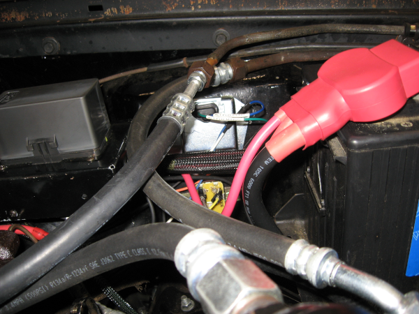
The final step was to install the voltage regulator in its final position and replace the test harness with production wiring.
As seen in this picture there is little room for the voltage regulator and poor access. Despite this I was able to locate it and drill new mounting holes. I really need to get a right angle drill. And smaller hands…
New voltage regulator – the silver box
The new voltage regulator requires two wires. I really didn’t want to run another wire – adding wires to a sleeved harness is a lot of work. The new voltage regulator doesn’t have the dedicated ground wire that the old one does – so why not repurpose the old ground wire as the new field wire? This simply required putting new terminals on each end of the wire – along with updating the labels on the wire so I won’t confuse myself in the future.
To ensure that the voltage regulator is well grounded I added a new ground wire from the updated chassis ground system to the case of the voltage regulator – this is the same ground that the headlights are using. I checked the grounding of the alternator to chassis ground and it was good, around 0.3 ohms.
With everything connected and the wiring double checked it was time for the first moment of truth. Fire up the engine and check the voltage. 14.5V-14.6V – just a touch high, but within specs.
I’ve been here before, so on to the real test – the test drive! After a good test drive, including Interstate driving, the voltage registered a steady 14.4V-14.5V. Again, on the high side but within specs.
I’m declaring success and moving on to the next project.
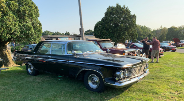
Introducing the Imperial Deathstar, a black 1963 Chrysler Imperial. This is one of the largest production sedans ever built, and arguably the best luxury car of its day.
Join me what will probably be a never-ending saga of grease, aching muscles, and an empty wallet as I work to restore this over 50 year old survivor to a reliable cruiser.