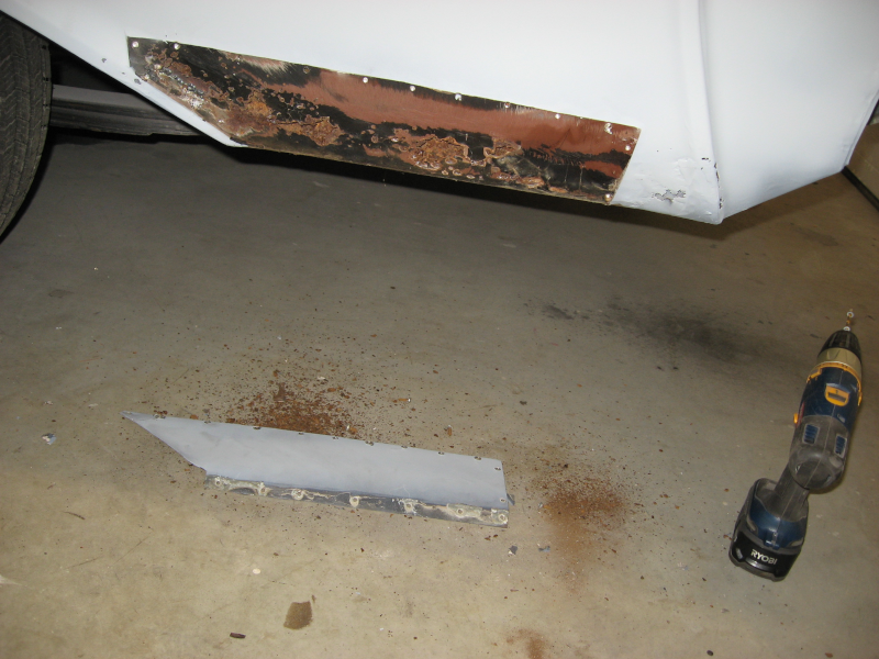
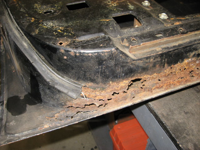
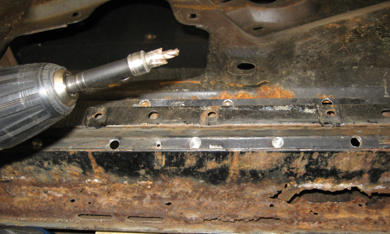
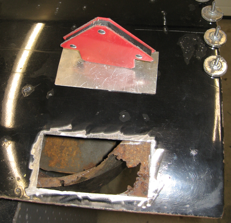
After several weeks of travel it was back to the Imperial. First job: remove that nasty “patch” mentioned in the previous article I’m a Stripper… The pop rivets drilled out easily, but for some reason the flange on the bottom of the patch was attached by screws. Which were firmly rusted in place. After application of two different impact guns, vice grips, and high explosives (actually the high explosives were only considered; I ended up substituting strong language instead), the screws finally came out and the panel came off.
Under the original “patch” panel
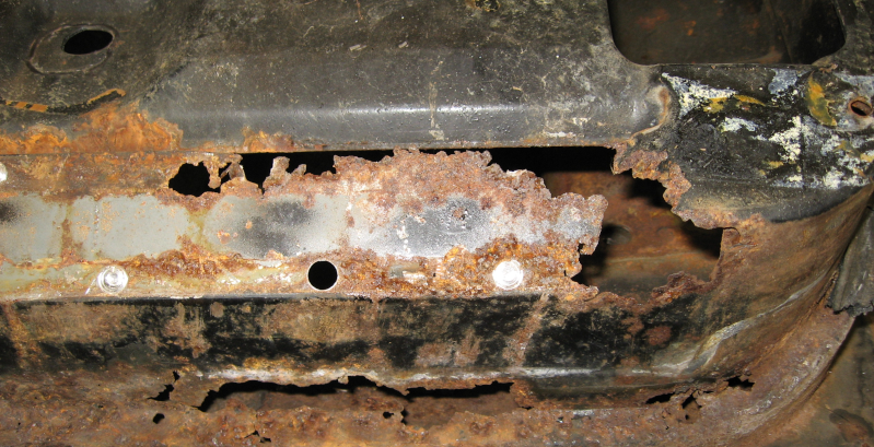
Yeah, that’s not good. That whole area needs to be cut out and replaced with solid metal. There are also rust holes several inches beyond the “patch” panel. Of course this leads into an area with complex curves.
You know the drill by now: divide the large complicated damaged area into several smaller and simpler areas. Create and fit a cardboard template for the first area. Repeat until you have a template you are happy with. Transfer the cardboard template to sheet metal and cut it out. Form this new sheet metal patch to the contours of the car. When you are happy with the fit, trace around the patch panel onto the car body and then cut out the damaged area. Grind the edges of the patch and the body until you have a good fit. Stitch weld the patch in place and grind the welds. Stitch weld the gaps and grind down the new welds. Repeat until all of the seams are solid.
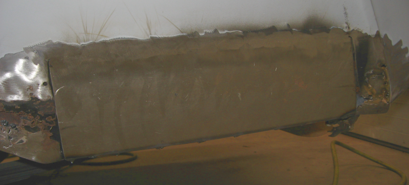
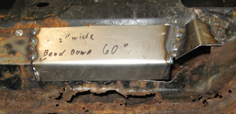
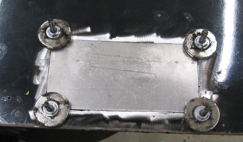
The first patch covers the center of the rusted area. This area is curved in a single direction and is fairly easy to fit.
Center patch fitted and welded in place
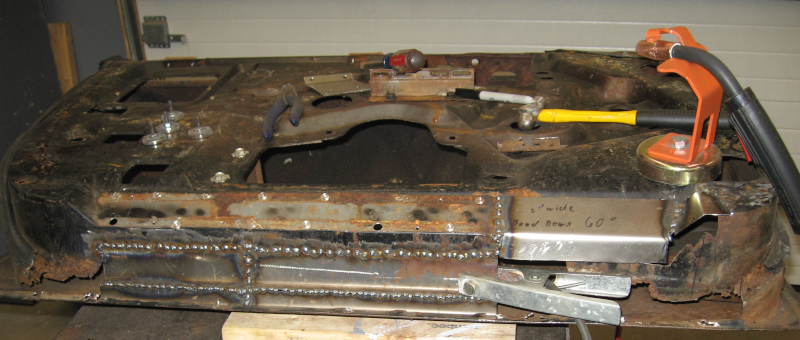
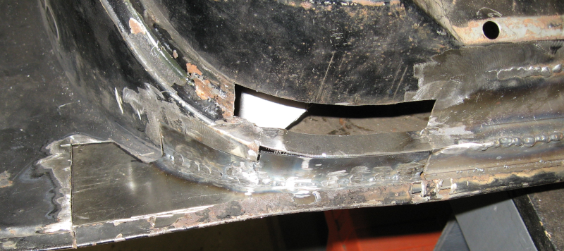
Repeat this process with additional patches. This incremental approach lets you fit each new patch to both the previous patch and to the shape of the car body – you don’t cut out any of the car body until you have fitted the patch that will replace it. Building up complex shapes out of small pieces makes it fairly straightforward to match the complex curves around the wheel well and the back bumper reveal.
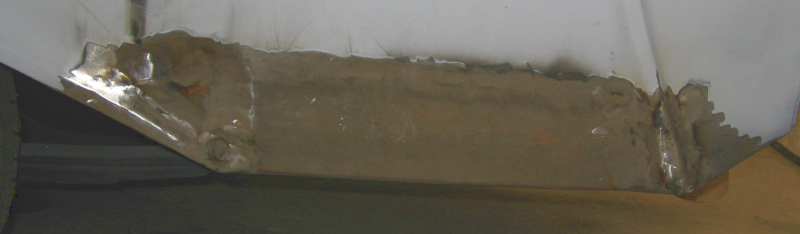
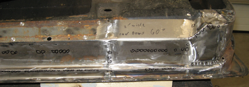
When everything is done you have a solid patch that replaces all of the rusted areas and matches the original curves and body lines.
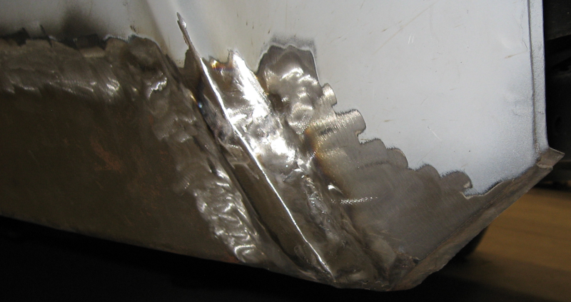
Finished patchDetails of rear bumper character lines
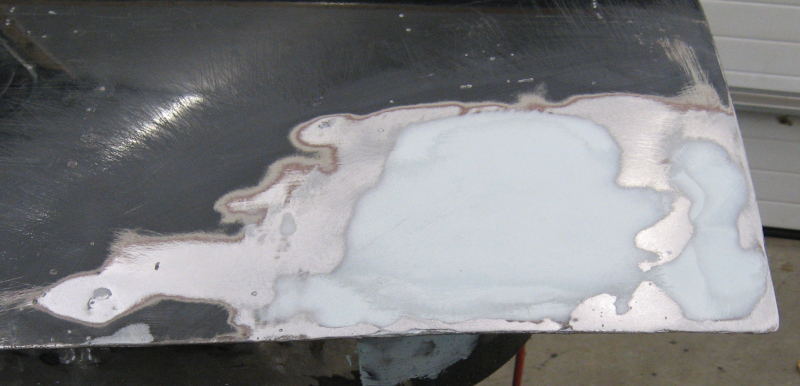
Can you tell exactly where the metal was replaced? If not that is a good sign! While the metal forming is finished the work isn’t done. The new metal, especially the seams, aren’t completely flat and smooth. Body filler is applied to the low areas and sanded down, leaving a nearly finished surface to be perfected later using high build primer and block sanding.
Completed patch with body filler
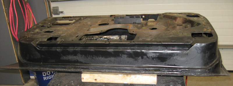
The other side of the car wasn’t much better, so lather, rinse, and repeat the process with a similar end result.
Passenger side patch
I’m fairly happy with how these patches turned out. The tricky areas, namely the wheel wells and the ridge for the rear bumper, are very close to the original – I don’t think you will be able to tell where the work was done. I had a bit of warping along the welded seam of the main patches – this is common with relatively flat panels. Normally you would planish the welds to minimize this, but planishing requires access to both sides of the weld for hammer and dolly work. The warping wasn’t severe and was corrected with minimal amounts of body filler but it still annoys me.
The frustrating thing about repair work like this – if you do a good job no one will know that you did anything…
In the last article, Hoodie 2, we finished working on the hood. Which meant it was time to move on to the rest of the car.
Paint serves many functions. It is the most visible part of a car, driving your perception of the car. It is a protector, keeping the underlying metal from rusting. And it is an opaque barrier, hiding whatever is beneath – whether it is solid metal or Bondo… This last part is critical with old cars.
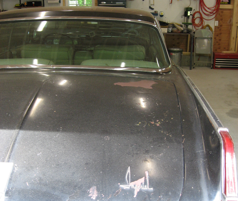
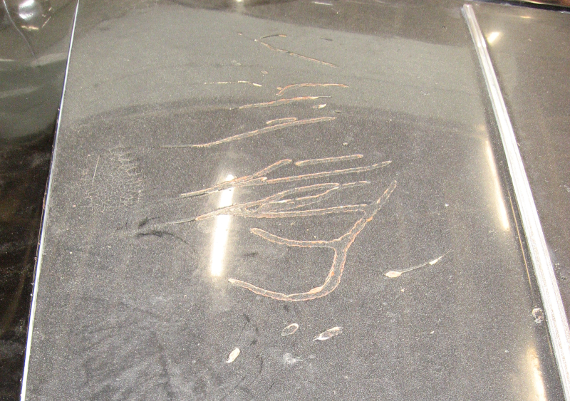
I’ve already covered several discoveries hidden by paint and trim. And strongly suspect that there are more hidden surprises lurking under that sinister black paint. There are several bad areas in the paint – it looks like something was left on the hood which ate into the paint:
Damaged paint on hood
Several spots on the trunk lid are down to primer:
Damaged paint on trunk
There are areas where the paint is badly cracked:
Cracked paint
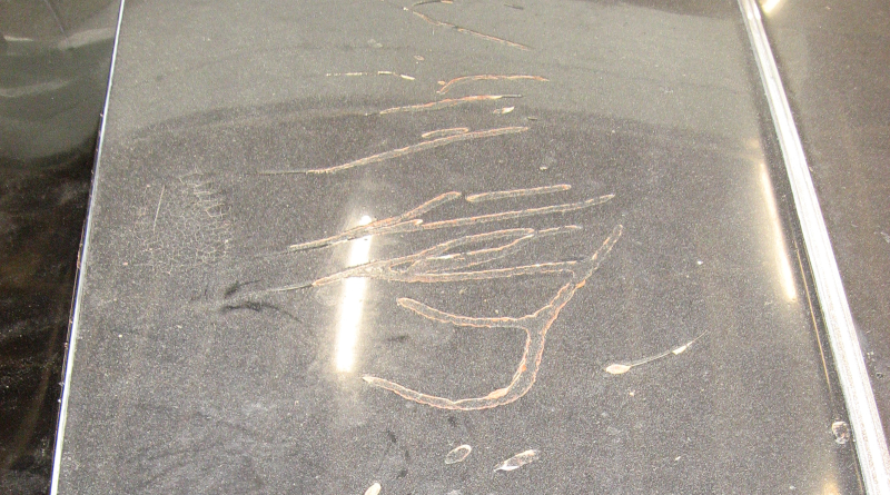
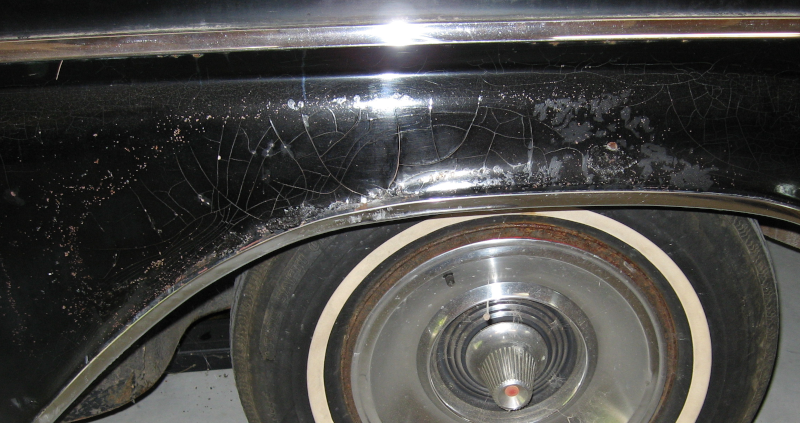
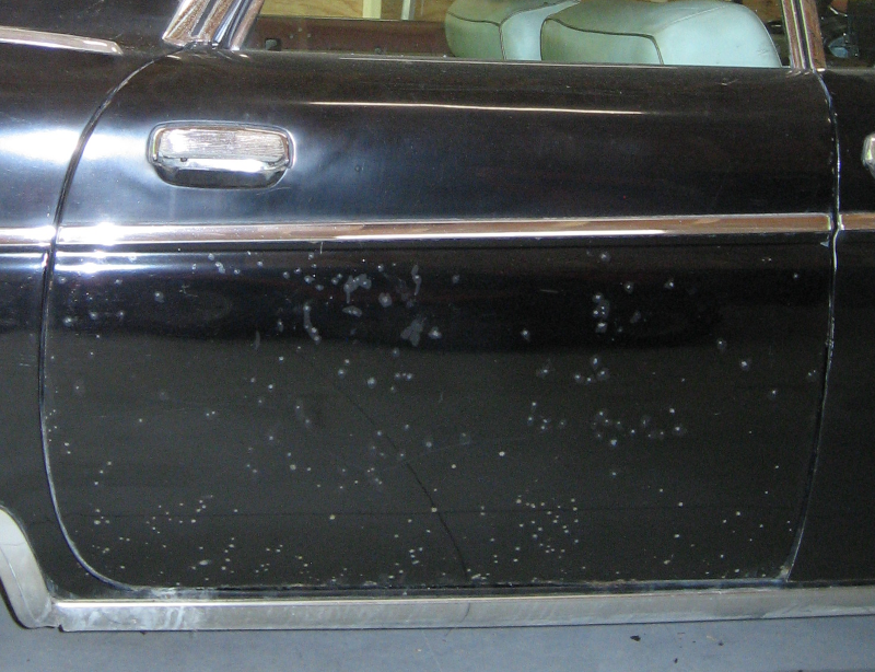
And most interesting are the numerous speckles on both sides of the car – with the exception of the front passenger door, which we know was previously repaired. These speckles go completely through the paint, there is grey metal at the bottom of the holes that looks like lead, and the holes haven’t rusted. My theory is that the car was shot with a shotgun – repeatedly. I would really like to know more about the history of this car!
Shotgun blast?
Between the known issues and the unknown issues the only way to prepare the Imperial for paint is to completely strip the entire car down to bare steel, repair as needed, and build up a foundation for new paint. I have to become a stripper – a paint stripper!
But how?
An orbital sander is much, much too slow. A flap disk takes paint off quickly but damages the metal. Chemical paint strippers are incredibly messy and don’t work well – EPA regulations have made paint stripper less toxic and less effective than it used to be. What is left?
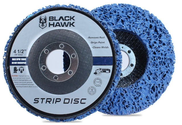
Research turned up something called strip disks. These are basically a sponge like material with abrasives embedded in the plastic and are designed to go on an angle grinder. The theory is that they are abrasive enough to remove paint, the open mesh keeps the abrasive from getting clogged with paint (an issue when using sandpaper), and they don’t damage the underlying steel.
Paint stripping disk
Worth a try, so a box of BHA Easy Strip Discs was ordered. Many choices are available; this one was chosen based on a combination of good reviews and a mid-range price. My theory is that the cheapest choice is cheap for a reason, the expensive choices may be either good or simply over priced, and that medium price ranges are often the best balance of quality and cost.
With a strip disk mounted on the angle grinder, an N95 face mask strapped firmly in place, and safety goggles perched on my nose I cautiously approached the Imperial, ramped the grinder up to 11,000 rpm and applied it to a test area.
The strip disk worked great! It quickly and completely removed the paint and left the underlying metal undamaged. In fact you could still see the various imperfections in the surface of the steel. This will work!
Well, “quickly” is relative. We are talking about removing paint at the rate of square inches per minute. A single door takes about half a day, and a fender takes half a day to a day. Reaching the center of the roof and trunk lid is a major stretch – and the grinder gets heavy very quickly when waving it around at full extension of your arms. Bracing yourself in position so that you can stretch that far uses leg muscles that aren’t used for any other purpose – as they remind you for the next three days… Stripping paint off of a large care is literally a pain!
The bad news is that it took over a week of incredibly dirty days and two boxes of strip disks to complete this miserable task. I ended each day looking like a racoon once I took off the face mask and safety goggles. I left my clothes in the basement to avoid tracking dirt through the house and had to run them through the washing machine twice to completely remove the paint dust from both the clothes and the washer. The water going down the shower drain looked like something out of an Alfred Hitchcock movie – in black and white, of course!
The good news is that the paint was completely removed, giving me a solid foundation for a good paint job.
The results?
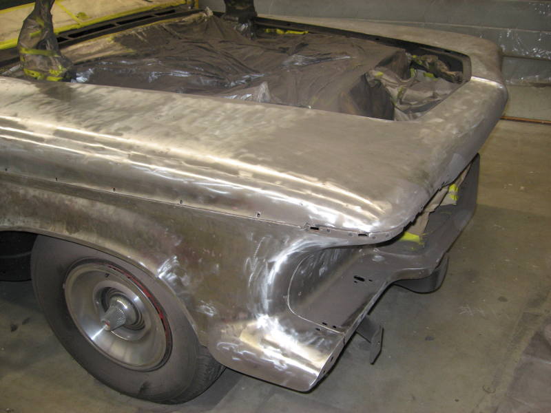
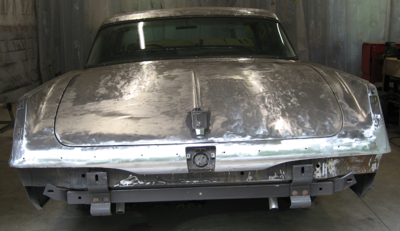
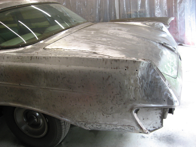
Front clipSide and roofTrunkRear Quarter Panel
The strip disk turns the paint into paint dust creating a massive mess. How massive? As previously mentioned this car has about 64 acres of surface area. It requires about a gallon of primer and 1-1/2 gallons of paint to cover it, or about 2-1/2 gallons total. Automotive paint is roughly 80% solvent and 20% solids. This means that there is about 1/2 gallon of solid paint on the car which is turned into dust. Plus any Bondo that was hidden under the paint – and Bondo is applied much thicker than paint. Of course dust takes up more space than the equivalent solid, so we are looking at creating 1-2 gallons of paint dust – which is blown off the car at high speed by the angle grinder. This dust ends up EVERYWHERE! On the car, on the floor, in the back yard where it has been sucked out by the vent fan, on the protective curtains, on the shop tools, and everywhere in the shop.
Not to mention in the shop vac. The trusty shop vac was used almost continuously to try to manage the paint dust. The car and floor were vacuumed repeatedly. I emptied the shop vac and cleaned the shop vac filter at least 4-5 times during this project.
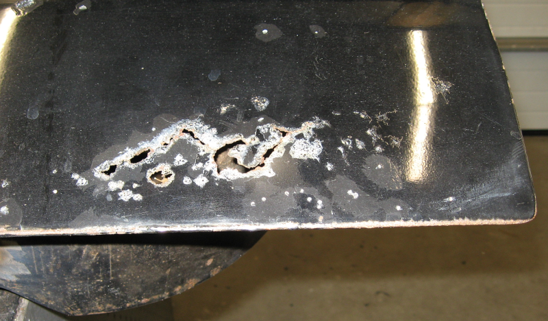
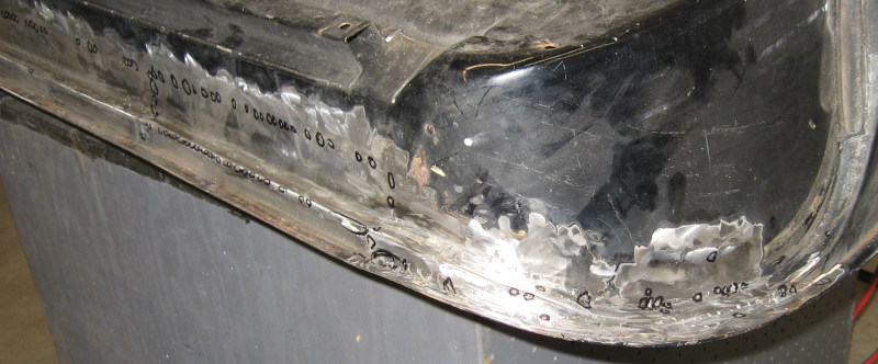
With all of the paint removed from the Imperial and the car, floor, table, shop equipment and other miscellaneous surfaces vacuumed it was possible to take stock of the actual condition of the body.
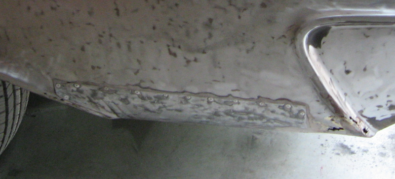
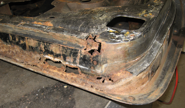
Uh Oh – what is that at the bottom of the quarter panel previously hidden under a layer of bondo?
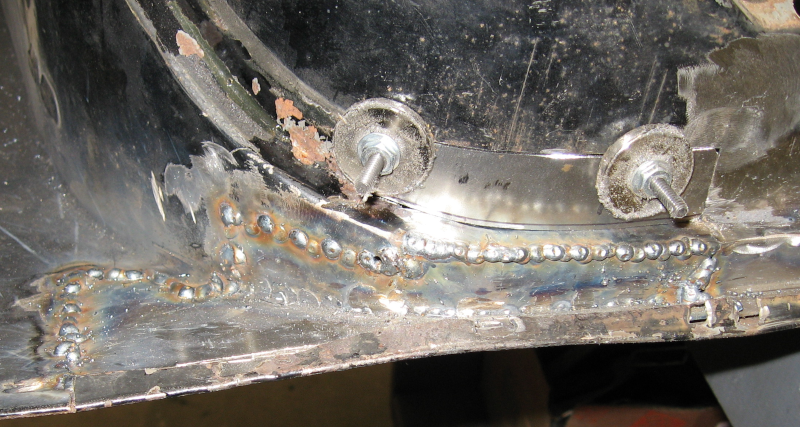
Surprise!
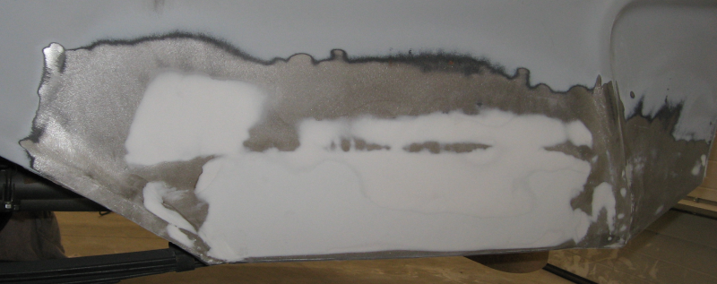
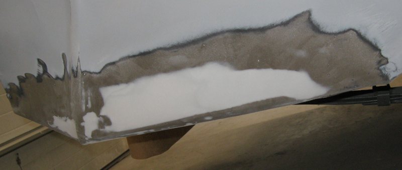
Surprise! One of the worst ways to “repair” rust – just pop rivet a piece of sheet metal over the top of the rusted area, cover with Bondo, and paint to match. Plus other rust holes that had just been Bondo’d over.
Actually, this was almost good news. I had seen evidence of this patch panel on the bottom of the quarter panel and was afraid it covered a much larger area. Stripping off the paint showed more rusted areas on the other quarter panel, although without the nasty patch.
This whole area will be cut out and new patches welded in place. Only a skim coat of body filler will be needed, unlike the 1/4″+ applied over the riveted patch. It will take time to patch these areas properly – but it will be done properly this time!
Other details were also revealed. Several small dents turned up that need to be fixed as well as a couple of larger dents. The shotgun blasts will need work. I’m not nearly as close to being ready for paint as I had hoped to be.
But, overall, the car is solid and in good shape. There were fewer surprises than I really expected. The rusted areas hidden under the paint are in areas that are almost guaranteed to rust on older cars. There is surprisingly little rust in the front fenders and the rocker panels are solid. Even though I’m complaining about what was hiding under the paint, I really can’t complain.
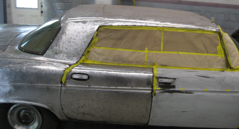
Just to add to the entertainment, I won’t be able to work on the car for several weeks. It can’t be left as bare steel as it will start to rust again. Since there is paint dust everywhere I had to vacuum everything, remove all of the old masking, vacuum again, wash twice with solvent, mask everything again, wash with solvent, go over it with a tack rag, and spray a coat of primer. Which I did.
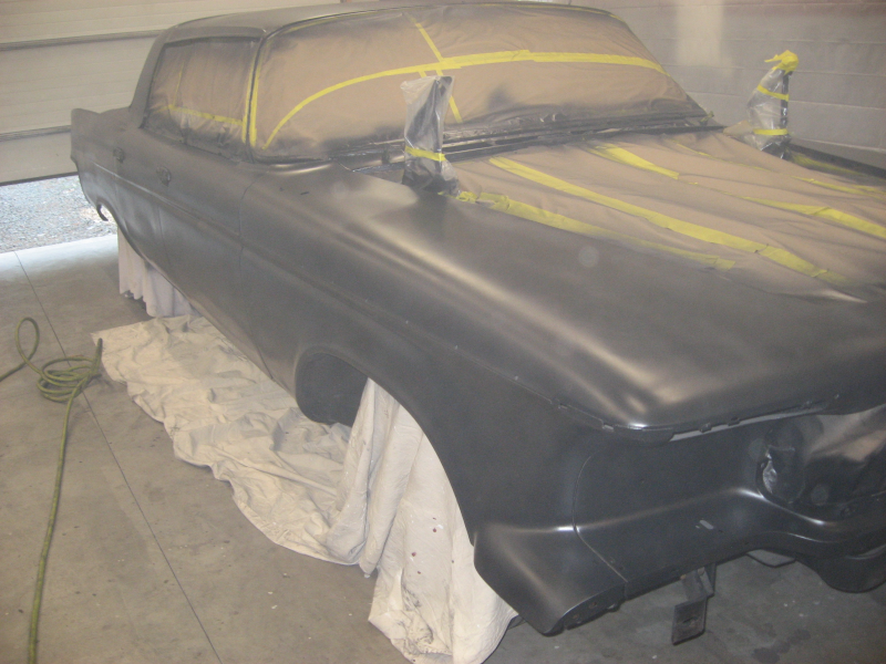
Imperial sprayed with epoxy primer
The epoxy primer leaves a flat back finish that is popular today, especially on hot rods. It looks positively evil on this car, and I mean that in a good way. I’m tempted to black out the chrome trim, put it back together, and drive it like this! I’m not going to, but it is tempting…
When I get back to work on the car the plan of attack is rust repair followed by dent repair. I have to figure out how to deal with the shotgun blasts – hopefully high build primer will take care of this. The whole car will be sprayed with high build primer and the surface perfected. Once the surface is perfect a final coat of epoxy primer will be applied and then the car will be ready for the paint shop.
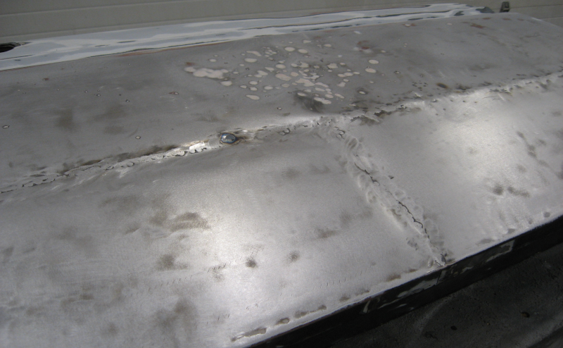
With the bottom of the hood done in Hoodie I flipped the hood over and tackled the top. The top of the hood has bothered me since I got the car – something had been laid on top of the hood that attacked the paint, there were areas where the paint was badly cracked, and multiple large stone chips. Basically it looked horrible.
Hood Problems
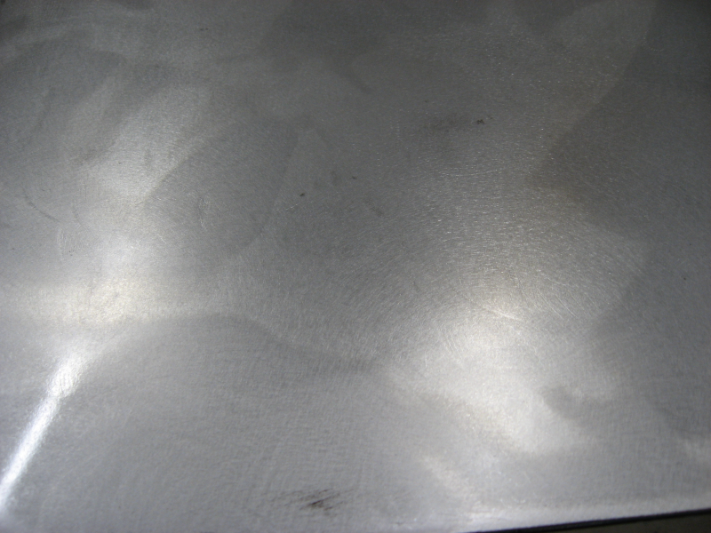
The hood needed to be completely stripped of paint, skim coated with body filler, and primed. The DA sander I used to strip paint off the door in Door Four Debacle worked but was very slow. A flap disk on an angle grinder quickly stripped all the paint off the hood – but at a cost. Even though I was careful the flap disk noticeably gouged the surface, leaving marks that would clearly telegraph through the finished paint. Fortunately I was already planning to skim coat the hood, which will hide the gouges. The flap disk is clearly too aggressive for paint removal. Something else is needed for the rest of the car – hopefully something faster than a DA sander…
Paint stripped with flap disk and smoothed with DA sander. Gouges still show.
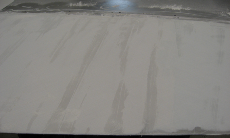
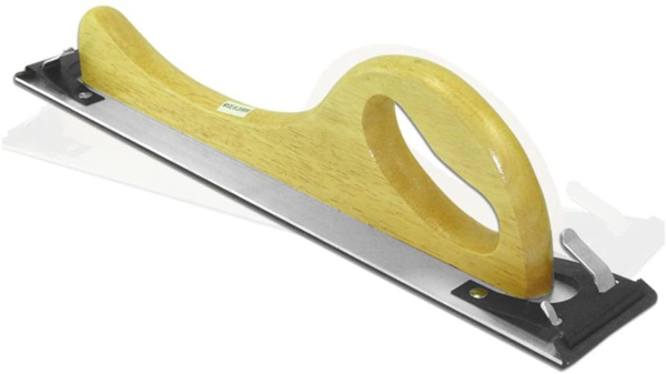
With the paint gone a thin coat of body filler was applied and worked with the body board to produce a completely flat surface. Here you can see the high areas have been sanded down and low areas remain.
Light areas have been sanded; dark strips are low spots.
Working large areas of filler with a body board is a huge amount of work. After a couple of hours of back breaking (and shoulder breaking and biceps breaking and wrist breaking) work to get partially done I called it quits for the day and headed inside to order power tools.
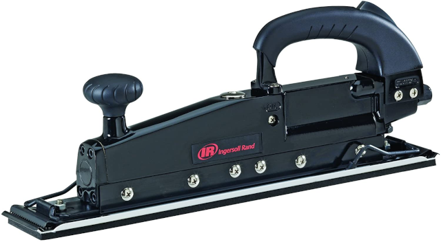
A jitterbug, more properly a straight line air sander, is the tool of choice in body shops. A jitterbug is fast – too fast if you don’t know what you are doing. The general recommendation is to use a manual body board until you learn how to work filler. I decided that I had learned enough with the manual board and was ready for the pro tool!
Jitterbug
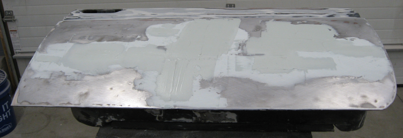
The jitterbug loaded with 36 grit sandpaper made short work of rough shaping the body filler. The bare metal represents the high spots and the filler has filled in the low spots. The hood was already fairly flat, so the filler is less than 1/16″ thick. After finishing the shaping with 36 grit, 80 grit sandpaper was loaded onto the jitterbug to get rid of the deep scratches left by the extra coarse 36 grit sandpaper.
Skimcoat of filler shaped with jitterbug leaving a completely flat and straight surface.
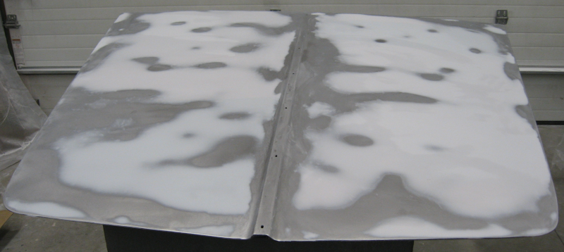
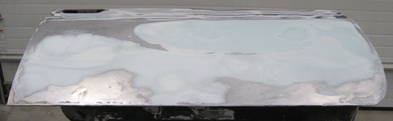
With the rough shaping done the next step was to perfect the surface. Two coats of epoxy primer were sprayed onto the hood to seal it and provide a foundation for high build primer. Two or three coats of high build primer were applied, followed by a light guide coat. The DA sander was loaded with 180 grit sandpaper and sanded until all of the guide coat was gone.
Hood with high build primer. Guide coat on left, sanded guide coat on right.
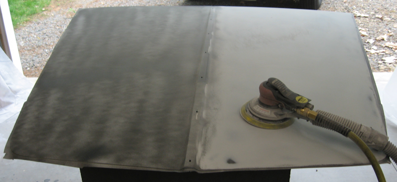
The main purpose of the high build primer is to fill in the sanding scratches left by the 80 grit sandpaper in the previous step. After sanding with 180 grit another guide coat is sprayed and a final pass with 320 grit sandpaper to remove the 180 grit scratches finishes sanding.
You might notice that the DA sander has two hoses attached to it – an air hose and a mystery hose. The large hose is attached to a shop vac and pulls sanding dust through holes in the sanding disk. This new sander greatly reduces the amount of sanding dust released onto the air and should minimize cleanup. We will see how it works out – initial results are encouraging.
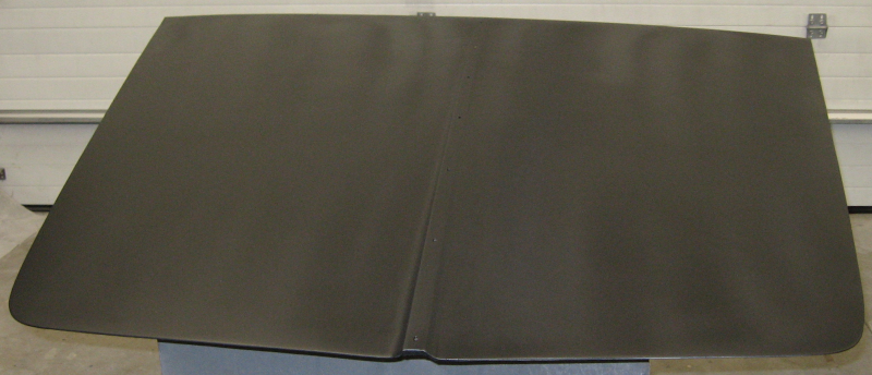
Two coats of epoxy primer seal the high build primer and provide a surface ready for the actual paint.
Finished hood with epoxy primer
There is a little bid of banding in the epoxy primer because I sprayed it with a small finish gun that makes it difficult to smoothly cover large surfaces. In the future I need to use a full size spray gun for these larger jobs. The small gun is great for smaller areas and provides better fine control – you just need to use the right tool for the job at hand.
The hood came out quite nice. All that is left is the other 90% of the car… Which we tackle in I’m a Stripper…
After finishing the last door in Door Four Debacle it was time to move on to the next rust damage I had been avoiding – a hole in a rib in the hood inner frame.
Wrestling the hood off of the car is normally a two person job, but only one of me was available. No problem! Drag out the engine hoist, hook it up to take most of the weight, and I can handle the rest. Demonstrating the wisdom that comes with age (or perhaps expensive and/or painful mistakes…) I quickly realized that you have to have people on both sides of the hood to control it while it is flying through the air. Desperate times call for desperate measures, so I asked She Who Must Be Obeyed for help. With two people guiding the hood it safely migrated off the car and onto the workbench.
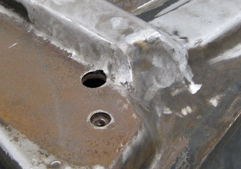
Unfortunately I didn’t get a before picture, but the hole was at the end of one of the pressed ribs in the hood frame, next to the hood hinge. This is a complex area: multiple curves at different angles and all edges have a large radius. A single face of the damaged area is joined to up to six other faces, and all of them have to match exactly. There is a reason I’ve been stalling on this job!
Good side of hood frame – what I want to end up with
My initial plan was to make a single patch panel to replace the entire area I had to cut out. This is elegant but very difficult to do… One of the key lessons learned on other patches is that you can create a single large, complex part out of multiple smaller and simpler parts. Further, you can start with one small part, weld it into place, and then fit the next part to it – bend, fit, mark, trim, precision sand the edge to fit, and then weld this new small piece into place. Continue like this across the entire part and you can build complex shapes that are quite precise.
One of the advantages of working with metal is that you can add (weld) and subtract (cut, grind, or sand) material freely until you are happy with the result. With patience and a willingness to re-do work you can achieve surprising results. After grinding welds smooth it is difficult to tell where repairs have been made. A bit of body filler, some high build primer, and a coat of paint and the result looks perfect! For certain values of perfect…
In previous repairs I was able to bend the patches by either using my (small) bending brake or simply over the edge of my steel fabrication table. This produced a small radius curve at the bend, but I was able to fit the patches to the surrounding structure. This approach just wouldn’t work on the hood.
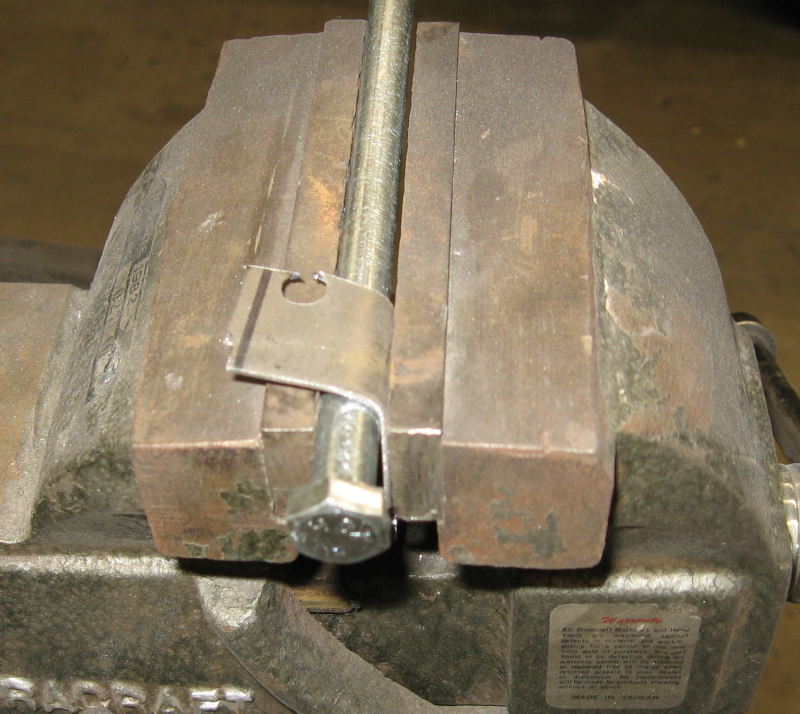
I needed something to match the radius of the curves. After mulling this over for a while I realized that I had an assortment of bolts of various sizes. OK, this could work.
With this approach in mind I cut out the damaged area and started to work. The first question was what is the radius of the existing edges? I grabbed a handful of bolts, cut out small test pieces of sheet metal, and bent the test pieces around the bolt. Holding the bolt and sheet metal panel for bending was an issue. The brute force approach was to simply clamp the bolt and metal part in a vise. This would be much easier with three hands… Doing it this way is slow, but acceptable for the small number of pieces needed for this repair.
Putting a large radius bend into a test piece
A 1/2″ bolt produced a curve the nicely matched the existing hood frame. The rest of the bolts were returned to their storage boxes to make sure I didn’t get confused when making parts. Of course I haven’t actually done anything like that in the past!
With the problem of bending the edges to shape solved the job became relatively straightforward: Pick an edge to start with. Cut, bend, and fit a piece of metal to that edge, perhaps starting with a cardboard template. Once happy with the fitment, weld the new part into place.
Then choose the next edge to work on. Cut, bend, and fit another piece of metal to match this new edge and to the part previously installed.When happy with the fit, weld the new part into place. Repeat this process until you once again have a complete frame section with no holes.
The corners where the parts meet were basically spherical and presented special challenges. The new pieces being welded in were left somewhat long. After welding them in the corner was worked with a body hammer until it had the desired spherical shape. Cutting notches in the corner and careful hammer work produced acceptable corners. With more practice I should be able to do even better. Once the corners were worked into shape they were welded up – both the edges and the notches that can been cut into them. The corner was further shaped with careful grinding, resulting in a smooth and convincing result.
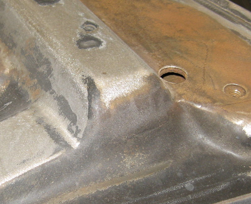
Hood Frame Repair
Compare this with the other side of the hood frame which received no repairs:
Hood Frame from other side; no repairs
Not a perfect match but solid and much better than a rust hole.
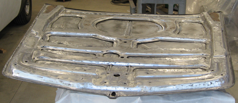
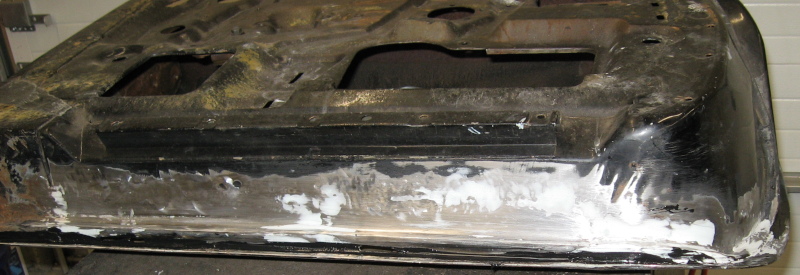
With the rust repairs done I took advantage of the opportunity to strip the paint off the bottom of the hood. This was partially done as a dry run for working on the rest of the car. Stripping the paint with an orbital sander works but is tedious and slow. Not ideal for the 63 acres of paint on the rest of this car…
Bottom of hood stripped of paint
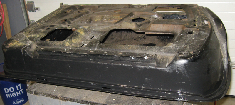
After removing the old paint the hood received two coats of epoxy primer and two coats of finish paint.
While the end result looks good, I should have taken a bit more time and applied body filler to the patched area before painting. If you look closely you can see some divots and scratches from the grinder that have telegraphed through the paint – exactly the sort of thing that body filler and primer/filler hide. I need to remind myself that this is on the bottom of the hood and that no one else will ever notice or care…
Next: preparing the side of the hood that shows in Hoodie 2.
In AfterCoolin’ I put off tackling the last door by finishing work on the air compressor. After running out of excuses there was no choice but to move on to the last door.
While the bottom of the door looked good that unfortunately wasn’t definitive. One way to check sheet metal for rust is to probe it with an awl or screwdriver. If you can punch a hole the metal is rusty and needs to be cut out and replaced. The bottom and edges of door four were solid – a pleasant surprise. This meant that all I needed to do was clean and lubricate the window tracks, upgrade electrical wiring, and add the power window relays. Should be an easy one day job!
As I removed the window assembly I noticed what looked like a seam in the outer door skin. One that was tack welded in place with large gaps between the weld dots. Above this seam was a collection of dimples, divots, and dents in the door skin. Hmm, time for a closer examination…
And discovery that the door was solid because it had already been repaired.
Close examination showed that the bottom third of the door skin had been replaced and the bottom of the door extensively patched. There was clearly body filler on the door, but no way of telling how thick. Based on the evidence it looked like the door had rust and then had been hit. The rusty metal had been replaced and the solid metal hammered more or less back into place. Not a completely horrible job, but I wasn’t happy with it. Especially concerning was the partially welded seam. I couldn’t just leave it without knowing what was actually under the paint.
After muttering the appropriate lamentations and deprecations it was time to pull the door off the car and deposit it on the bench. The first step was to find out what I was really working with. Since the paint was hiding everything it had to go. My tool of choice was an 80 grit sanding disk on an orbital sander. After a couple of hours of work the door was down to bare metal and body filler. The body filler also needed to go, but was taking forever with the orbital sander. A coarse sanding disk on an angle grinder made short work of the old filler, at the cost of covering the entire workshop with a thick coating of grinding dust.
The good news was that the patch panels had been well fitted – tight seams with virtually no gaps. They just needed to be welded up. Back to the familiar routine – stitch weld, grind, look for pinholes, and repeat. After a few hours the seams were solid.
Door with seams welded
While the door was now solid, it looked horrible – dents, waves, ripples, and bulges. The seams weren’t flat, which meant the welds couldn’t be ground smooth. You can see some of the old body filler in dents above the weld – it was solid so I didn’t spend a lot of time trying to grind it out of the bottom of each small dent.
If this were a fender I would start working with hammer and dolly to get the entire surface flat – or at least close to it. Unfortunately the inner door skin greatly limited any hammer work. The surface was fairly close, so time to break out the body filler!
Checking the door with a straight edge showed where the lowest spots were. These low areas were filled with a thin coat of body filler and then worked with a body board and 36 grit sandpaper. A body board is an 18″ long by 2-12″ wide flat board with sandpaper attached. It allows you to get a flat surface across dents and waves and is the first tool in preparing for paint.
Body Board for sanding
If the surface is flat everything will be evenly sanded with the body board. If it isn’t flat, the high spots will be sanded down and the low spots left untouched. When dealing with dents and valleys the high spots will be sanded to bare metal and the low spots left untouched. When this happens you add more filler to the low areas and sand some more.
I prefer to apply thin layers, so several applications were needed to get the entire door flat. At this point the surface is close to flat but has deep scratches from the 36 grit sandpaper. 36 grit is more for shaping than finishing. The next step is to apply a thin coat of filler to the entire door – 1/16 of an inch or so. This coat is worked with the body board with 80 grit sandpaper.
Second – or maybe third or fourth – coat of filler
Here you can see the second coat of filler. If you look closely at the edges of the first coat of filler you can see how they have been feathered into the sheet metal leaving no visible transition. This is critical to a smooth panel in the final paint.
This is where you will start to use guide coats. A guide coat is a misting of black paint over the filler. If the surface is absolutely flat all of the guide coat will come off evenly when sanded with the body board. Low areas will be highlighted in black surrounded by body filler color. Scratches will show up as black lines. If you see any traces of the guide coat you need to continue sanding.
Once everything looks good with 80 grit you apply another guide coat and continue with 180 grit sandpaper. Additional thin coats of filler are applied as needed.
Final application of body filler
The end result is a flat panel. Bare metal indicates areas where the sheet metal is flat, lack of guide coat shows that the body filler is flat, and the translucent edges of the body filler show smooth feathering into metal.
While the panel is flat it isn’t ready for paint. The surface is finished, now it needs to be perfected. Two coats of epoxy primer are applied to the door to seal it and provide a foundation for the next step, followed by 2-3 heavy coats of high build primer. This high build primer is thinner than body filler and goes on smoothly. A guide coat is applied and the door is sanded with 240 grit sandpaper on a sanding block.
If some guide coat is left after sanding another coat or two of high build primer is applied and sanding continues. When you have a good surface with the 240 grit sandpaper, apply another coat of high build primer and sand with 320 grit. Once you are done with 320, give it a final sanding with 400 grit paper to eliminate sanding scratches. Yes, there are still 400 grit sanding scratches – but these are far to fine to telegraph through the final paint and will never be seen.
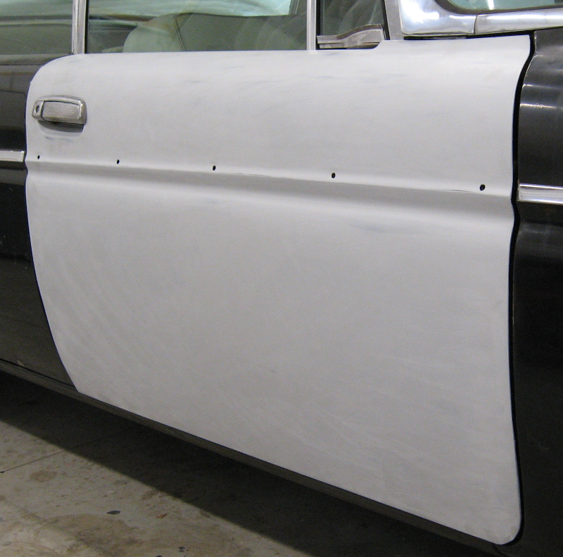
The end result of all this work is a perfectly flat and “laser straight” door that will not show any sanding scratches in the final paint – exactly what is needed for a black car! Black is the worst color for showing any imperfections in preparation. The saying in the automotive world is “if it is perfect, paint it black”.
Finished door mounted on the car. There is some sanding dust on the surface that needs to be cleaned off.
This needed bodywork turned the door into a two and a half week job rather than the single day originally planned. To be fair other things happened during this time like adding bay curtains to the workshop, but it was still a lot of extra work.
Whoever did this door originally did a reasonably good job. The door was solid and looked good. I was quite happy to note that I did a better job on the other doors that I worked on – better fit and finish, more attention to details, everything butt welded instead of overlapped, patches trimmed flush even inside the door where they couldn’t be seen, and all supporting brackets replaced. Maybe there is hope for me! In addition the inside of the door was painted with epoxy primer, all seams were sealed, and sound deadening mat installed.
The worst part of all of this body preparation work? It has to be done to the entire car. All 64 acres of the body of this monster need the same tender loving care before it can be painted. Krud.
After fighting rust in the previous article Door Three “Delights” I decided to finish off another workshop project to upgrade my air supply.
One of the problems with air compressors is moisture. A basic physics fact is warm air can hold more moisture than cooler air. When there is high humidity this shows up as water in the tank – which has to be regularly drained out – and moisture in the air lines. When compressed air is used it expands. When it expands the air cools. When the air cools any moisture in the in the air condenses into water in the air lines. This water damages air tools, ruins paint jobs, and causes general problems.
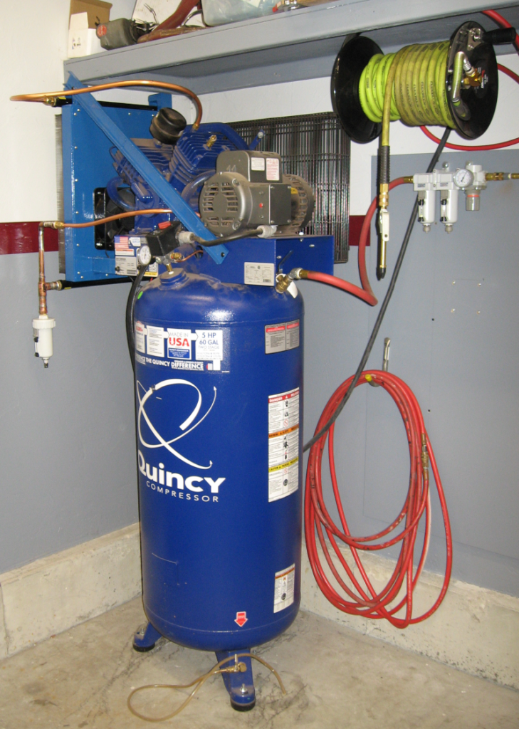
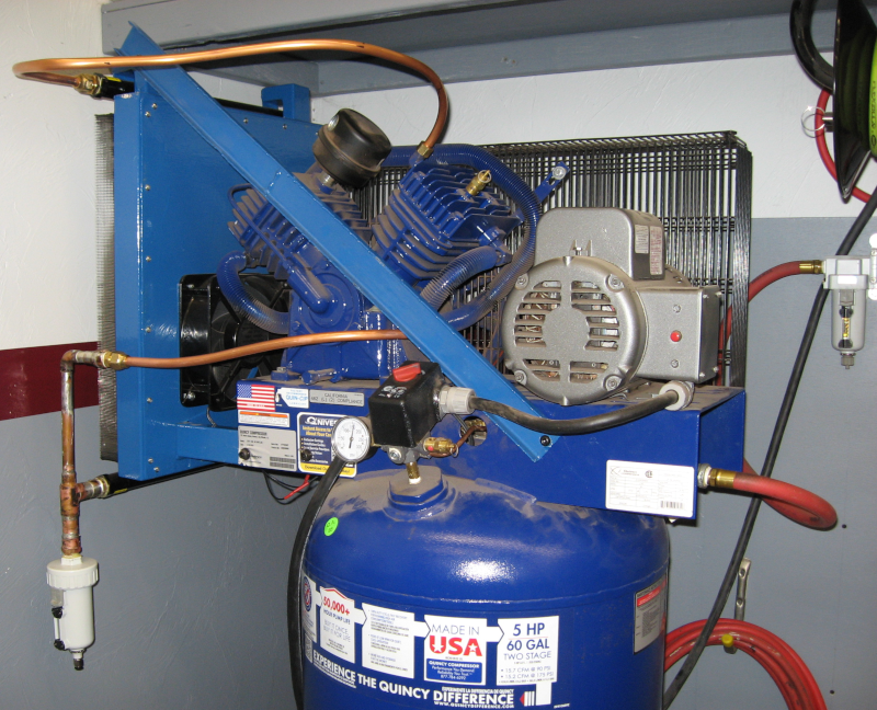
Air compressor with after cooler
Moisture isn’t much of a problem when the humidity is below about 50%. I never thought of New England as being especially humid, but over the last couple of summers I discovered that the humidity is a consistent 70%-80%, with frequent excursions into the 90%+ range.
This caused major problems with painting. I had to use expensive dessicant filters to remove the moisture – and these quickly became saturated and wouldn’t work any more.
One solution is to add an after cooler between the compressor and the air storage tank. This after cooler cools the hot air coming out of the compressor causing most of the moisture to condense out as water where it can be drained away before entering the rest of the system.
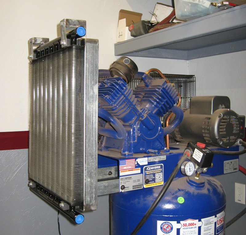
Of course it was Garage Journalthat introduced me to after coolers. They are called after coolers because they are installed after the air compressor and before the air storage tank. After reading several threads there I decided to use a Hayden Automotive 1290 Heavy Duty Oil Cooler. This is basically a large high pressure/high temperature radiator
One of the recent fabrication projects involved building a mounting frame out of 1″x2″ steel tubing to hold the Hayden cooler and bolt to the air compressor.
Testing fitting mounting frame and Hayden 1290 cooler to air compressor
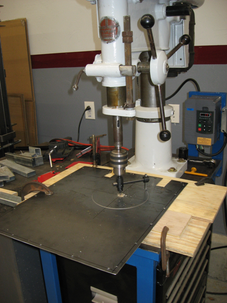
This frame was closed with sheet metal and an 8″ 220V fan added to draw air through the Hayden cooler. Normally an automotive cooling fan would be used, but automotive fans run on 12V DC and the air compressor runs on 220V AC. The fan was connected to the motor output terminals on the pressure switch so that it only runs when the compressor was running.
Fly cutter on drill press cutting large hole for cooling fan.
After test fitting everything the after cooler was disassembled, the frame painted, and then put back together and installed on the compressor. Actually connecting the air lines was delayed a bit by tracking down the plumbing fittings needed.
After acquiring the needed fittings the original copper lines connecting the compressor to the air tank were removed and replaced with new soft copper lines going to the after cooler.
The after cooler includes an automatic drain which will – wait for it – automatically drain the water that condenses in the after cooler and prevent it from reaching the tank.
With the final plumbing installed and all fittings tightened it was time to fire up the compressor and see if it worked.
Finished after cooler
The compressor started to run – always a good sign! – and pressure began to build – another good sign. The pressure built to the full 165 psi and turned off. Nothing blew out, yet another good sign. The new fittings were checked for leaks with soapy water and no leaks were found.
And there was much rejoicing!
Did it work? The basic test is output temperature from the compressor and input temperature to the pressure tank after the after cooler. Air gets hotter when it is compressed and can reach up to 350 degrees F coming out of the compressor. I monitored the output of the compressor which reached a maximum temperature of 315 degrees. The maximum temperature going into the tank was just over 90 degrees – a reduction of over 200 degrees! But still at least 30 degrees over ambient temperature.
The initial test was done without the cooling fan working – I wanted to make sure all of the plumbing was solid before making the electrical connections. After hooking up the cooling fan I cycled the compressor again. Initial temperature going into the tank was 59 degrees. Maximum temperature observed while the compressor was running was 62 degrees – a really excellent result!
The air was extremely dry today – humidity was only 16% – so no water was collected in the automatic drain valve. I expect the drain valve to get a workout as soon as the humidity goes back up to 90%+.
Update (August 2, 2022): The air compressor has been getting an extensive workout. I just dumped out close to a gallon of water from the automatic drain. There was virtually no water in the tank and just a trace of water in the original water filter. On humid days I’m no longer getting a fine mist of water from the air tools like I was before. The aftercooler is a success and a very worthwhile project!
Next: time to quit stalling and tackle the last door in Door Four Debacle.
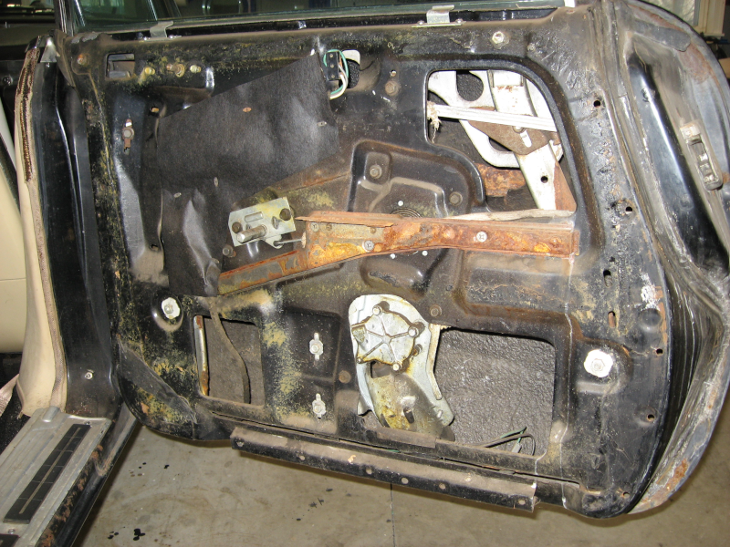
After upgrading the power windows on the first two doors in Electrical 13: Relay That Window! it was time to stop stalling and start working on the drivers door. This door has the worst rust on the entire car, so it will be a bit of a project. After removing the glass – including the vent window – the door was pulled off the car and set on the bench. Which revealed the full challenge.
In addition to extensive rust across the bottom of the door, the rust wraps up the sides in areas with complex curves. This is where the door fits to the car and where the weatherstrip is, so the repairs have to precisely match the original shape.
The good news (the eternal optimist said…) is that there is enough metal left to retain the original shape. This makes it possible to replace the rust with solid metal bit by bit and match the original shape. Tedious, but much easier than working from nothing!
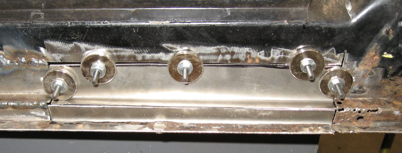
The starting point is the brace going across the bottom of the door. The brace itself is in good shape, but the rust goes well under it. The brace has to come out so that the substructure can be replaced. This involves locating and drilling out the spot welds on the brace.
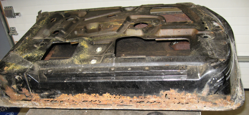
Once the brace is removed the full problem is revealed:
Yeah, that needs some work. Fortunately only straight bends are needed here. Measure the area to cut out, cut and weld in patches, and this part of the door is stabilized for the next steps.
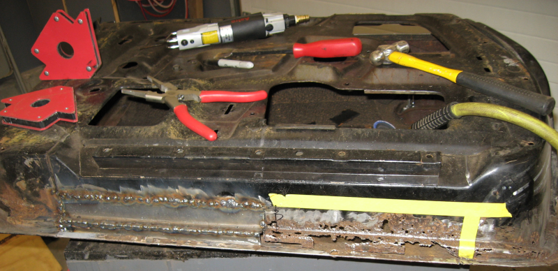
Next work across the bottom of the door, replacing the flat sections first:
The drivers door is the only one with rust in the outer skin, so the door is flipped over. A patch panel is fitted, held in place with magnets, and welded.
The fit on this patch panel isn’t too bad – maybe I’m getting better! Or, more realistically, less bad…
With the door skin patched, flip the door back over and start working on the curved section. The process remains basically the same – cut and fit small patch panels, cut out the rusted section, tack weld the patch in place, and move to the next patch.
Repeat the process on the front corner of the door and then time to start the process of grinding the welds, identifying gaps, and welding and grinding until everything is solid.
The brace that was removed earlier was welded back on using the original spot weld holes as locators. This completed the structural repairs. While the complex shapes of the inner door structure were rigid enough to hold their shape during welding, the relatively flat outer door skin had just enough warping to be noticeable. The double skin in this area kept me from being able to properly work the metal. A skim coat of bondo and careful shaping with an auto body sanding board made everything perfectly smooth again. This is a very thin skim coat – roughly 1/16″ – 1/8″ maximum thickness.
Door seams were filled with seam sealer and a coat of epoxy primer was applied to keep the new metal from rusting:
With the metal work done the door was ready to go back on the car. The big question: Will it fit?
Yes! Yes, it still fits! And there was much rejoicing!
With the first hurdle overcome it was time for the true test: would the door still close with the new weatherstrip installed? The weatherstrip was fitted and held in place with tape. And the door closed! And opened and closed and opened and closed. Success! Sweet, sweet success.
With repairs on the door complete the next step will be to re-install the glass and adjust everything. And apply the power window upgrades to this door.
The last electrical article looked at dash lighting in Electrical 12: Dash It All!. It is now time to deal with a sticky situation – specifically, power windows that stick going up and down.
Power windows are the among the worst cases for old car electrics – the motors require high amperage and are fed through long wires and small switches. Over time the window mechanisms become harder to operate, requiring even more power from the motors. At the same time the wiring degrades, reducing voltage available to the motor and making it work even harder. The result is that power windows simply don’t work well on old cars – when they work at all.
In my case one of the windows (drivers door, of course…) doesn’t work at all, two windows barely work, and the fourth window is slow and doesn’t always go all of the way up.
Part of the work on the doors includes cleaning and lubricating the window mechanisms. This certainly helps, but doesn’t go far enough to solve the problem.
Really solving the problem requires completely replacing the existing power window wiring with something that can handle the power requirements.
Relays will be used to provide power directly to the window motor – basically the same thing that was done with the headlights when they were upgraded. The existing switches still control the windows. But instead of handling the 20-30 amps that the motor draws, the switches will now trigger the relays and only have to handle less than 0.1 amps. The existing wiring and switches are easily able to handle 0.1 amps.
The window motor requires two relays – one for up and one for down – which makes the wiring somewhat more complex than the headlights.
Power for the relays will be provided by a new dedicated 12 gauge power line that is run directly from the relays to the fuse box. Power will now come from a shorter run of heavier gauge new wiring – the motor will now get full voltage and full power.
Since I’m paranoid – in other words, I have experience… – the relay upgrade will be done as a series of incremental steps with testing at each step. Thus the first step is to build a test harness to allow testing the window motors outside of the existing window wiring. This test harness will go through a series of modifications and upgrades as the build proceeds.
The initial test harness was simply two wires connected to the battery. There are two wires to the motor – I was pretty sure that the motor case is ground, and you apply +12V to one wire to go up and +12V to the other wire to go down. But it could also be reversing plus and minus between the two wires for up and down.
With the two wires connected to the to the battery, the negative wire was held against the motor case and the +12V wire was applied to one of the wires to the motor – and the window went down! +12V was applied to the other wire and the window went up. OK, motor wiring is confirmed.
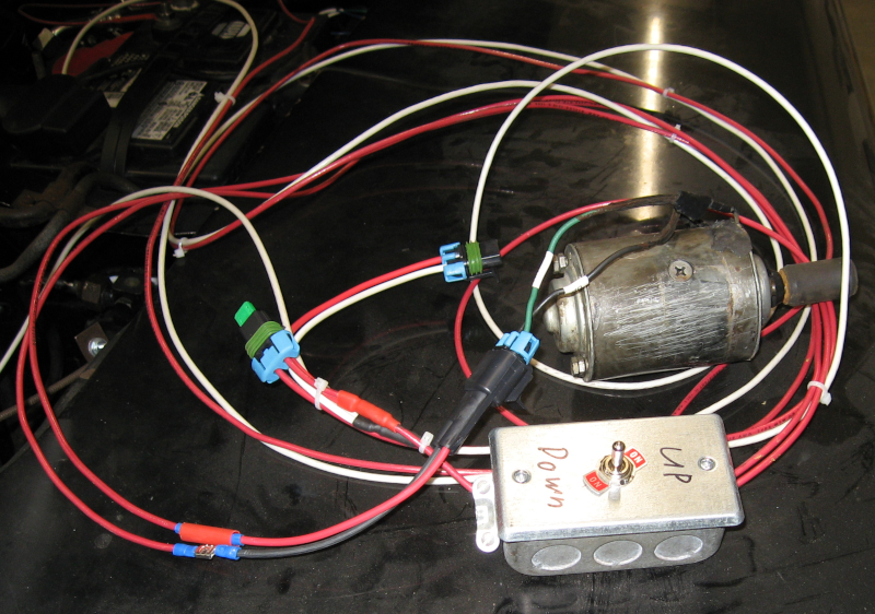
Next a two way switch was added to the test harness. Technically this was a dual pole/dual throw momentary contact switch, also known as DPDT momentary contact. This allowed using the switch to control up and down on the motor. Connectors that mated with the motor were added. The test harness is long enough to reach from the battery to each door and to the workbench, making it easy to operate the windows either on the car or on the bench. This was convenient since you need to move the windows up and down to remove the glass. As previously mentioned I’m paranoid, so a fuse was also added.
Since the test harness will also be used to implement the new dedicated power wiring, a matching power connector was added. The test harness can be used to directly power and control the window motor in the car or on the workbench as well as provide power to the relays.
Power Window test harness connected to a window motor
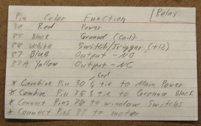
With motor operation verified and the test harness ready to go it was time to build the relay setup. The first step was to lay out the design on paper, double check it, and determine how to connect the relay wires. I’m using Bosch style relays which have five wires – trigger/source, ground, power in, power out normally open and power out normally closed. Since the relay should provide power when the switch is turned on the normally open (NO) output is used and the normally closed (NC) output was sealed off.
The relays I’m using came with sealed sockets and pigtails – this makes it easy to wire them up. The good news is that the pigtail wires are color coded. The bad news is that the color coding didn’t comply with standards… Notes that include pin number, color, function, and wiring instructions kept me from becoming excessively confused when making the four relay packs (one for each window).
Relay wiring card
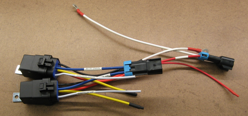
I wired up the relays on the bench – it is much easier to work on the bench, and it gave me the chance to double check everything before installing. Note the labels on the wires – this minimizes mistakes and makes it much easier to troubleshoot in the future.
Window Relays Wired
The test harness and a voltmeter allowed complete testing on the bench. No mistakes were found in the wiring. OK, OK – no mistakes were found when the relay packs were ready to install in the doors…
The window motor was originally grounded through the door skin. Since it is very little additional work to run two wires instead of the planned one wire for power, a dedicated 12 gauge ground wire was added. This ground will tie directly into the upgraded grounding system under the dash and is bolted to the power window mechanism frame which is connected directly to the motor. This also provides a convenient high quality ground point for any other potential electrics in the door.
The new power and ground wires are connected to the relays using a waterproof Metri Pack 280 connector. The relays are sealed, and all wiring connections are sealed with marine grade heat shrink tubing – the result is that there shouldn’t be any corrosion in the power window system.
The motor originally used non-sealed Packard 56 connectors, which I replaced with more of the Metri Pack 280 connectors. When I cut the old connectors off and stripped the insulation, the wires were solid black with corrosion. Sandpaper and electrical contact cleaner cleaned up the wire ends and the new sealed connectors should prevent more corrosion in the future.
The test harness was plugged in to provide temporary power to the relays and window operation tested. It worked!
With everything ready to go I spent an hour or so making a bracket to mount the relays. I then tested window operation and watched the window hit the relays as it neared the bottom position. Actually I stopped the window just before it hit the relays. I’m getting paranoid about that sort of thing…
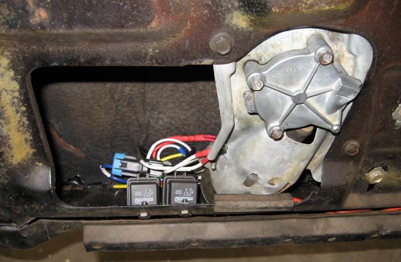
Studying the situation more, I decided that the relays could be mounted directly to the inner door skin. The relays were mounted in this new position, the window run down, and nothing hit. OK, one more problem solved!
Power Window Relays Installed
The window now goes up and down smoothly. It will need to be adjusted to fit the new weatherstrip I’m installing. This will probably be a nightmare; if it is I will do a post.
This process will be repeated for the other three doors.
I also need to finish connecting the new power wiring. As I do each door I’m running the new power and ground wires up to under the dash. The next to last step will be to connect all of the new power and ground wires and splice into the existing power window feed from the under hood fuse box.
The last step is to enjoy the new smoothly operating and reliable power windows!
I’ll confess – one of the reasons for doing all of the projects around the workshop has been a bit of stalling on actually working on the car.
In an early post I described the Imperial as being essentially rust free. Yeah, about that…
While the car is solid overall there are some problem areas. The doors need work – three of the power windows don’t work and the fourth one barely works. The locks on the back doors are frozen, most of the door weather stripping is missing, the door glass weather stripping is shot, and there is rust on the bottom of the doors. The driver’s door is in really bad shape, so I decided to start with the other doors and get some practice before tackling the worst one.
Pulling the door card off the back door shows some surface rust, but not too bad. The rusty brace will be cleaned and painted before it is re-installed.
Back Door
The door was removed from the car and the window mechanism taken apart, cleaned, and lubricated. This is the power window that works – the motor is in good shape, so cleaning, lubricating, and aligning the window mechanism and tracks should restore it to full function.
As expected the latching mechanism was partially frozen. Fortunately no rust, so a good cleaning and lubrication should be all that is needed.
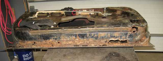
The door shell was lifted onto the workbench for closer examination. Not good; a fair amount of work is needed. The rusted sections need to be cut out and replaced with good metal. Two things to note: First, this is very common – water runs down the inside of the door, collects in the bottom, and is trapped. Second, this is one of the better doors…
Rear Door showing “tinworm” attack
The good news is that there is plenty of solid structure left in the door. This makes it easy to make patch panels that maintain the shape of the door. If large areas are completely missing it is difficult to make a precise replacement. This part of the door has to be precise – it is the sealing surface between the door and the body of the car.
The bottom of the door is fairly simple – it is flat with a few straight bends. It is a “Z” bend, which means I can’t make it as a single piece. The answer is to make it as two pieces with a single bend each and then weld them together to make the third bend. I have a small bending brake that can’t handle the whole length as a single part, so it will be done in two stages.
Cutlines are marked with tape – this gives you a straight line and can be re-positioned until you are happy with it. The old metal is cut out, patch panels are fabricated and fitted, and the new panels are stitch welded in place.
Sheet metal warps badly when welded, so you can’t run a continuous weld bead. Instead you briefly trigger the welding gun, producing a small dot or spot weld. You do this about every two inches, allow the metal to cool, and then add new weld dots between the existing weld dots. You repeat this until the entire seam is solidly welded. This approach minimizes the amount of heat applied to the sheet metal and reduces warping. You still get some warping, but it is easier to deal with.
This picture shows the first patch panel stitch welded in place and the second rusted area ready to cut out.
Door Repair In Progress
The second patch panel is cut and fitted. While most of the patch is fitted fairly well there are still some excessive gaps. I need to do a better job of fitting patch panels – one of the reasons for tackling the easier doors first! Magnets hold the patch panel in place for fitting – this makes it much easier to get things lined up. When everything is correctly located the corners will be tack welded to lock everything into place and then all of the seams stitch welded.
Second patch panel
After welding the weld bead is ground down flush with the surface. Done properly you won’t be able to tell that anything was ever done. When stitch welding it is common to have small gaps or pinholes between the weld dots. You can find these by shining a light behind the weld and marking any gaps. These gaps then receive a weld dot. Stitch, grind, and repeat until the entire weld is solid.
Pinholes that need more welding
The corner of the door was a problem. I spent over a day trying to make templates using just two patch panels and wasn’t able to get a good fit. I finally gave up on that and made several smaller patches. This proved much easier to do and actually ended up fitting quite well.
After the welding and grinding is finished you should have a finished piece that is ready for painting. I’m not there (yet!), so some body filler is needed. Fortunately not much – while I need to get better, this isn’t a complete hack job.
Door with body filler
To make sure this doesn’t happen again seam sealer was applied to all seams. This will completely keep water out of all seams in the bottom of the door. A coat of epoxy primer was applied to seal and protect the surface. The epoxy primer was also applied to the inside of the door – something that should have been done at the factory!
Door Primed
The metal work on this door is done. The next step is putting it back together. Unfortunately I’m waiting on some parts for that – hopefully they will show up soon.
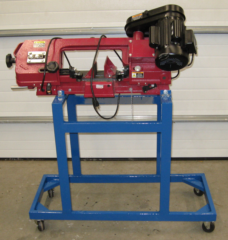
The horizontal bandsaw has been getting a real workout cutting up the steel tubing for various projects. While it does a good job cutting there are issues – mostly with the stand.
The included stand is the most criticized part of the bandsaw: it is flimsy, provides marginal support when the bandsaw is used in the vertical position, and is too low. In addition it is somewhat difficult to move the 140 lb. saw around.
The biggest issue is that it is too low. Since the main use is cutting up long pieces of stock you usually have to support the other end of the stock. I have a set of roller stands I use with the table saw, chop saw, drill press, and fabrication table for just this purpose. Unfortunately the lowest position on the roller stand is higher than the bandsaw. I ended up quickly welding together a temporary stand just for the bandsaw. This temporary stand is clumsy, awkward, and difficult to store – I’m looking forward to cutting it up and returning it to the stock pile!
All of these issues can be addressed with a new stand. The base was sized for stability – both side to side and when using the saw in the vertical position. The height was set to ensure that the roller stands can be used. And casters make it easy to move around.
BandsawBandsaw in vertical position
There are still a few things to do: First is adding a piece of plywood to the base for storage. Second is to add a pan to catch the metal particles from cutting and make cleanup easier.
Introducing the Imperial Deathstar, a black 1963 Chrysler Imperial. This is one of the largest production sedans ever built, and arguably the best luxury car of its day.
Join me what will probably be a never-ending saga of grease, aching muscles, and an empty wallet as I work to restore this over 50 year old survivor to a reliable cruiser.