
With the controller in place the next question was how to power it. The electrical engineer determined that we would need four 16650 Lithium Ion cells and a voltage regulator to make this work. He identified the parts he wanted to use and sent me the part numbers.
The datasheet for the voltage regulator had a mechanical drawing with dimensions. OK, that gives me the information I need.
The batteries would go in two battery holders, each holding two cells. Tracking down the part number on the Internet I discovered one of the greatest advances of civilization in the last 20 years: dimensionally accurate downloadable 3D solid models of the parts! I knew that these existed, but this was the first time actually using them in anger.
Let me see… The battery holders needed to be mounted on a flat surface about “this” big. Play with geometry for a few minutes and I had a rectangle the needed size positioned between the Orb ribs. Extrude it about 0.080″ thick and I had a mounting plate for the battery holders fused into two of the ribs.
Position two of the battery holders on the mounting plate. Project the mounting holes from the battery holder model to the Orb inner structure model. It all fits and looks good.
Rotate the Orb around and add a mount for the voltage regulator to the back of the battery mounting plate. The voltage regulator is a tiny 1″ x 1″ circuit board with components sticking up. Design a slot for it to slide into with plenty of room on both sides for air flow – voltage regulators can produce a fair amount of heat.
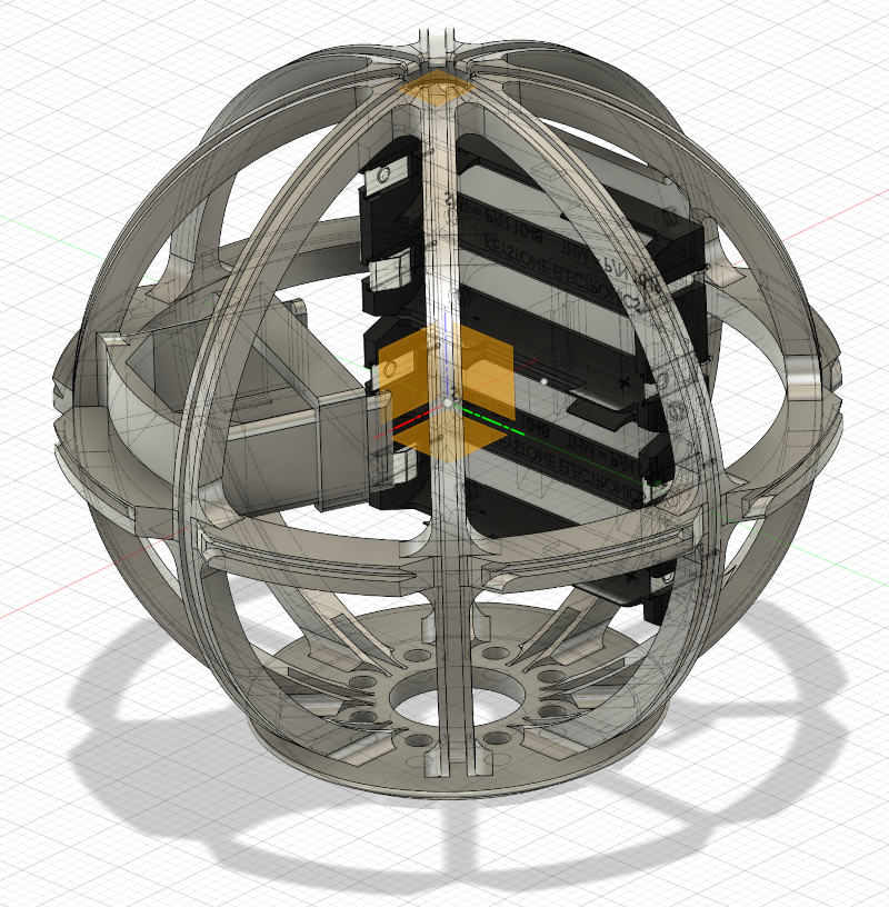
Assuming the actual production parts fit the Orb should be ready to go!