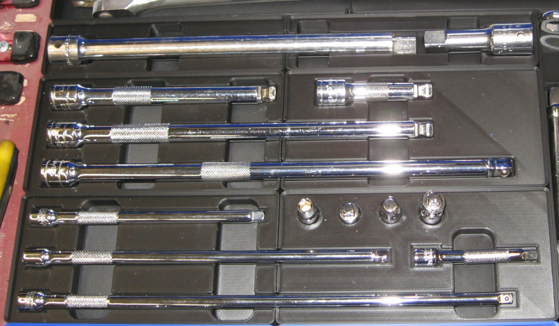
To effectively use sockets you often need extensions. I have a combination of random extensions from the past 50 years which are piled together plus a good set of 3/8″ extensions in a molded factory tray. I prefer using these good extensions, both because they are good and because I can immediately grab the one I need out of the tray.
Based on the previously described strategy of selective upgrades I ordered a set of 1/4″ socket extensions from Tekton.
With extensions in hand (actually, they were piled on the desk next to my CAD workstation) I went through the drill of laying them out, determining what size Gridfinity bin was needed to hold them, and starting the design process.
Creating the outlines was simple: First create a solid bin using the Gridfinity Bin Generator. The extensions are too long to print as a single piece, so create two bins. Create a sketch on the face of the bin. Make two rectangles in Fusion, one for the head of the extension and one for the shaft. The head size was the same for all of the extensions.
The shafts of the extensions were all the same diameter but different lengths. I learned a new way to make these: Create a line the length of the extension from the mid point of one edge of the head – Fusion will select the midpoint of the line when you mouse over it and will lock the line to 90 degrees from the old one when you have the mouse close to 90 degrees. Click on the midpoint, drag the new line at roughly 90 degrees, release the mouse button, and type in the length of the shaft. Bingo! Done!
Select this line, select the offset command with offset both sides, and make the offset the radius of the shaft. Delete the original line or change it to a construction line and then add lines between each end of the offsets. Viola, you have an outline for the shaft. This is much faster and easier than the manual geometric construction techniques I had been using. I tend to go back to my old drafting board geometric construction techniques. Fusion fully supports this old approach, but it also has many additional powerful ways to build things. I have a lot to learn! And I’m making some progress. Slow, but the more you do it the better you get. Amazing how that works!
To add another extension you make a copy of the first extension. Add a dimension to the shaft length and then edit the dimension to change it to the new length. Fusion extends (or shortens) the shaft. The parametric constraints in Fusion make sure that both sides of the shaft are the same length, the ends of the shaft remain connected to the sides, and that the shaft remains connected to the head. Magic! Repeat this process until you have created outlines for alll of the extensions and then finish (close) the sketch.
I generally make the cutouts half the depth of the tool. Select all of the extension heads, extrude them one half of the diameter of the head, and subtract them from the bin. Then select all of the shafts, extrude them one half of the shaft diameter, and subtract them from the bin.
With cutouts for all of the extensions done create the finger reliefs. Create another sketch on the face of the bin. Determine where you want the finger reliefs and add rectangles across the bin. Close the sketch. Select all of the finger reliefs, extrude them, and subtract from the bin.
As a final step go through and fillet all of the sharp edges. Not absolutely necessary, but calms my finer engineering sensibilities.
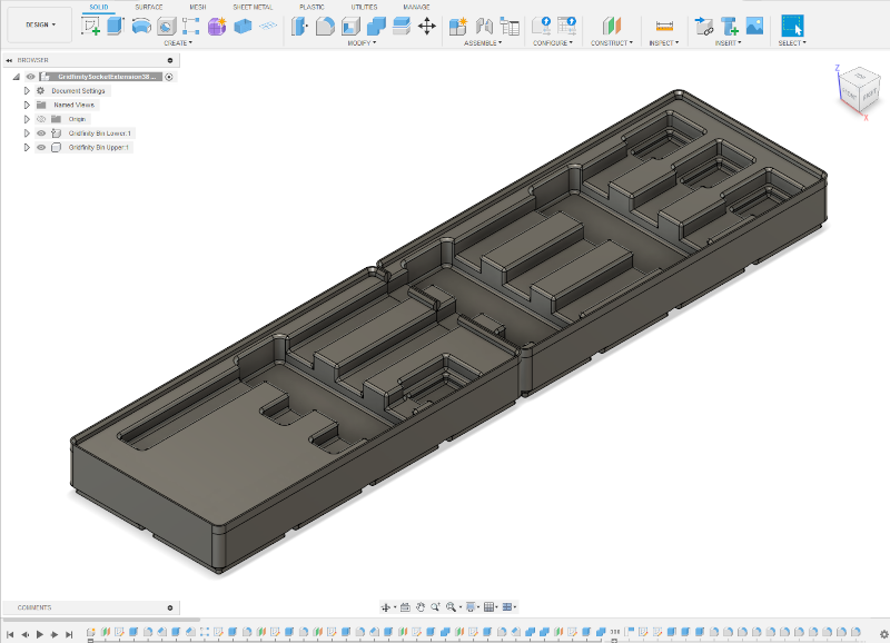
While the extension bins are too long to print as a single part the two bins in the design can be placed side by side on the printer and printed in a single print run.
That turned out pretty good. Now repeat the design process for the 1/4″ and 1/2″ extensions.